2026 Author: Howard Calhoun | [email protected]. Last modified: 2025-06-01 07:12:56
One of the ways to finish materials is milling. It is used for processing metal and non-metal workpieces. The workflow is controlled by cutting data.
The essence of the process
Milling is carried out for the purpose of deep roughing and finishing, the formation of a certain surface profile (grooves, grooves), cutting teeth on gear wheels, shape correction, artistic turning of patterns and inscriptions.
The working tool - the cutter - makes the main rotational movement. Auxiliary is the translational feed of the workpiece relative to its course. This process is intermittent. Its most important feature, which distinguishes it from turning and drilling, is the fact that each tooth works separately. In this regard, it is characterized by the presence of shock loads. It is possible to reduce their influence, taking into account a rational assessment of the situation and the selection of regimes.

Basic concepts of milling machines
Depending on the way the spindle is located and the cutter is mounted in it, on the types of actions performed and on the methodscontrol, distinguish the main types of milling equipment:
- horizontal;
- vertical;
- universal;
- CNC milling machines.
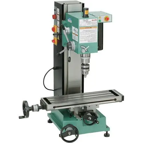
Main components of a vertical milling machine:
- The bed in which the gearbox is located, which regulates the rotation of a vertically mounted spindle and a cutter mounted on it.
- A table that includes a console with cross rails for mounting and moving the workpiece and a feed box that regulates feed movements.
In horizontal milling machines, the tool is fixed horizontally. And universal ones have several varieties.
There is a universal horizontal equipment, which is characterized by the presence of a turnover table and, thereby, expanding the range of possible work performed. In addition, there is a wide-universal one, which has both spindles in its structure and allows for all types of milling.
CNC milling machines are distinguished by the availability of software and computer control. They are designed for artistic processing of workpieces, including those in 3D format.

Classification of cutters
Cutters are cutting tools. The main physical parameters by which they are evaluated are: height, diameter, chamfer and relief values, circumferential step. There is a huge variety of them, distributed according to various criteria:
- according to the type of surfaces that are processed (for wood,plastic, steel, non-ferrous metals, etc.);
- in the direction of rotation - right and left cutting;
- depending on design features - solid, brazed, folding (have insert knives), welded;
- shape: conical, cylindrical, disc;
- Depending on the working conditions and requirements for the cutting part, they can be made of various materials. These include: carbon tool and high-speed steel (alloyed, with a high content of tungsten), hard alloy (durable - for roughing, wear-resistant - for finishing). Common options are when the body is made of carbon or high-speed steel, and the knives are plug-in carbide;
- depending on the purpose: cylindrical, end, end, slotted, cut-off, shaped.
The most informative features: cutting edge material and purpose.

Types of cutters for flat surfaces
To remove layers of material on horizontal, vertical or inclined planes, cylindrical and end mills are used.
The tool of the first type can be solid or with attached knives. Large solid milling tips are designed for roughing, and small ones are for finishing. Insert knives for folding cutting heads can be made of high speed steel or equipped with tungsten carbide blades. Carbide cutters are more productive than those made from alloy steel.
End is used for elongated planes, its teeth are distributed on the end surface. Large folding ones are used for wide planes. By the way, to remove chips from difficult-to-machine refractory metals, the presence of carbide knives is mandatory. To use these groups of milling devices, a significant width and length of the product is needed.

Types of artistic milling tools
To give the material a certain profile, apply a pattern, form narrow recesses, end and disk milling nozzles are used.
End cutter or grooving cutter is common for cutting grooves, narrow and curved planes. All of them are solid or welded, the cutting part is made of high speed alloy steel, hardfacing can be applied, and the body is made of carbon steel. There are low-start (1-3 spirals) and multi-start (4 or more). Used for CNC machines.
Disk is also a groove cutter. It is applicable for grooving, grooving, cutting teeth on gear wheels.
Artistic milling is carried out on wood, metal, PVC.

Types of edge cutters
Chipping corners, giving them a rational shape, modeling, splitting the workpiece into parts can be implemented using spline, angle and shaped milling nozzles:
- Cut-off and slotted has the same purpose as the disk, but are more often used for incisions and separationextra parts of the material.
- Corner needed for part edges and corners. There are single-angle (only one cutting part) and two-angle (both conical surfaces are cutting).
- Shaped is used for complex designs. May be semicircular or concave. Often used for profile cutting taps, countersinks, twist drills.
For almost all types, a one-piece steel construction or folding, with the presence of plug-in carbide knives, is possible. Carbide cutters have a qualitatively higher performance and duration for the tool as a whole.

Classification of types of milling
There are several classification features by which the types of milling are divided:
- according to the way the spindle and cutter are positioned, respectively, horizontally and vertically;
- in the direction of travel, on the opposite and passing;
- depending on the tool used, for cylindrical, end, shaped, end.
Cylindrical machining is applicable for horizontal planes, carried out using appropriate milling cutters on horizontal machines.
Face milling can be considered universal. It is applicable to all types of horizontal, vertical and inclined planes.
Finishing provides the necessary profile for curved grooves, drills and tools.
Shaping is carried out for surfaces with a complex configuration: corners, edges,grooving, gear cutting for gears.
Regardless of the type of work carried out and the materials being processed, the result should be distinguished by a high smoothness of the finish layer, the absence of notches, and the accuracy of the finish. In order to obtain a clean machined surface, it is important to control the feed rates of the workpiece in relation to the tool.

Up and down milling
When counter-type metal milling is performed, the workpiece is fed against the rotational movements of the nozzle. In this case, the teeth gradually cut into the metal being processed, the load increases in direct proportion and evenly. However, before the tooth cuts into the part, it slides for some time, forming hardening. This phenomenon accelerates the exit of the cutter from the working state. Used in roughing.
When performing a passing type - the workpiece is fed along the rotational movements of the tool. The teeth work shock under heavy loads. Power is 10% lower than with up-and-down milling. It is carried out when finishing parts.
Basic concept of milling work on CNC machines
They are characterized by a high degree of automation, workflow accuracy, high productivity. Milling on a CNC machine is most often done with end mills or end mills.
The latter are the most widely used. At the same time, depending on the material being processed, the corresponding type of chip forming, the specified software parameters,different end mills are used. They are classified by the number of helix starts that provide cutting edges and ditching.
Materials with wide chips are best milled with tools with a small number of starts. For hard metals with characteristic fracture chips, it is necessary to choose milling fixtures with a large number of spirals.

Using CNC cutters
Slow lead CNC cutters can have one to three cutting edges. They are used for wood, plastics, composites and soft ductile metals requiring fast wide chip removal. They are used for roughing workpieces, which are not subject to high requirements. This tool is characterized by low productivity, low rigidity.
Artistic milling of aluminum is carried out with the help of single-thread milling.
Two- and three-way ends are widely used. They provide higher hardness values, high-quality chip control, and allow you to work with metals of medium hardness (for example, steel).
Multi-start CNC cutters have more than 4 cutting edges. They are used for metals of medium and high hardness, which are characterized by small chips and high resistance. They are characterized by significant productivity, they are relevant for finishing and semi-finishing and are not designed to work with soft materials.
In order to choose the right tool for CNC machines, it is importanttake into account the cutting mode when milling, as well as all the characteristics of the surface to be machined.

Cutting conditions
To ensure the desired quality of the milled layer, it is important to correctly determine and maintain the necessary technical parameters. The main indicators that describe and regulate the milling process are operating modes.
The calculation of cutting conditions during milling is carried out taking into account the main elements:
- Depth (t, mm) - the thickness of the metal ball, which is removed in one working move. Choose it taking into account the allowance for processing. Draft work is carried out in one pass. If the allowance is more than 5 mm, then milling is carried out in several passes, while leaving about 1 mm for the last one.
- Width (B, mm) - width of the machined surface in the direction perpendicular to the feed motion.
- Feed (S) - the length of the workpiece movement relative to the tool axis.
There are several interrelated concepts:
- Feed per tooth (Sz, mm/tooth) - change the position of the part when turning the cutter at a distance from one working tooth to the next.
- Feed per revolution (Srev, mm/rev) - movement of the structure with one full revolution of the milling head.
- Feed per minute (Smin, mm/min) is an important cutting mode in milling.
Their relationship is established mathematically:
Smin=Srevn=Szzn, wherez - number of teeth;
n - spindle speed, min-1.
The amount of feed is also affected by the physical and technological properties of the treated area, the strength of the tool and the performance of the feed mechanism.
Cutting speed calculation
As a nominal design parameter take the degree of rapid rotation of the spindle. The actual speed V, m/min depends on the diameter of the cutter and the frequency of its rotating movements:
V=(πDn)/1000
The frequency of rotation of the milling tool is determined by:
n=(1000V)/(πD)
Having information about the minute feed, you can determine the required time for a workpiece with a length L:
T0=L/Smin
Calculation of cutting conditions during milling and their installation is important to carry out before setting up the machine. Establishing rational preset parameters, taking into account the characteristics of the tool and the material of the part, ensures high productivity.

Tips for determining modes
It is impossible to choose the ideal cutting mode when milling, but you can be guided by the basic principles:
- It is desirable that the diameter of the cutter correspond to the depth of processing. This will ensure that the surface is cleaned in one pass. Here the main factor is the material. For too soft, this principle does not work - there is a risk of chipping, the thickness of which is greater than necessary.
- Shock processes and vibrations are inevitable. In this regard, an increase in feed valuesleads to a decrease in speed. It is best to start with a feed per tooth of 0.15 mm/tooth and adjust as you go.
- The speed of the tool should not be as high as possible. Otherwise, there is a risk of reducing the cutting speed. Its increase is possible with an increase in the diameter of the cutter.
- Increasing the length of the working part of the cutter, the preference for a large number of teeth reduces productivity and quality of processing.
- Indicative speed values for various materials:
- aluminum - 200-400 m/min;
- bronze - 90-150 m/min;
- stainless steel - 50-100 m/min;
- plastics - 100-200 m/min.
It's best to start at medium speed and adjust it up or down as you go.
The cutting mode during milling is important to determine not only mathematically or using special tables. To correctly select and set the optimal parameters for the machine and the desired tool, it is necessary to operate with some features and personal experience.
Recommended:
High-speed trains. high speed train speed

Today there are express trains in almost every country. Let's see which is the fastest train in Russia and the world. Here is a rating of express trains that can reach speeds of over 300 kilometers per hour
Low Internet speed over WiFi: what to do? How to increase internet speed

The article explains why the Internet speed drops when using a wireless router
Rostelecom: reviews (Internet). Internet speed Rostelecom. Internet speed test Rostelecom

The Internet has long been not only entertainment, but also a means of mass communication and a tool for work. Many people not only chat online with friends using social services for this purpose, but also earn money
Cutting speed for milling, turning and other types of mechanical processing of parts

Calculation of cutting conditions is the most important step in the manufacture of any part. It is very important that the calculation itself be rational. This is due to the fact that for various mechanical operations it is necessary to individually select the cutting speed, spindle speed, feed rate, and also the depth of cut. A rational mode is one in which production costs will be minimal, and the quality of the resulting product will be as accurate as possible
Cutting mode during milling: calculation, definition, standards

How to determine the cutting mode when milling? For this, there are formulas, and tables, and graphs

