2026 Author: Howard Calhoun | [email protected]. Last modified: 2025-01-24 13:10:35
Milling is far from the simplest operation for processing metals and other materials, which is not always known in detail to the average person. The fact is that this process requires a special device called a cutter - it can be found at many enterprises, factories, plants. How does this process take place? In this case, it involves a cutting tool and a workpiece. The cutting tool is the cutter itself - it performs rotational movements, in contrast to the workpiece itself, which, with the help of the machine, performs translational movements towards the cutter. The result is a type of processing that would be difficult to replicate with any other tool. However, this article will not cover superficial information - this material is designed for those who are already more or less familiar with the milling process. The main and main topic here will be the cutting mode, that is, here it will be calculated and determined how exactly the cutter should function and which nozzle to use for it for specific types of metal of different hardness. To make it easier for you to understand the data that will be provided below, you should immediately find out exactly what concepts will be used here.
All you needknow
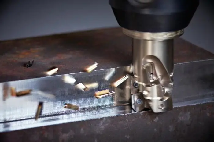
So, each paragraph will indicate which material is being considered, as well as its hardness according to the Brinell method - the most famous and common of all methods for determining the hardness of bodies. They are measured in HB, that is, Brinell hardness units. Next, the cutting speed will be determined, which is indicated in meters per minute (m / min). Here you should pay special attention to the fact that these are not cutter revolutions, but a completely different parameter. This parameter will be considered in several examples - if the material being processed by the cutter does not have any additional coating, and also if the cutter has different types of TI-NAMITE coating. And, of course, another very important milling parameter will be described - this is the feed per tooth. For people far from this sphere, this parameter may seem rather unusual, but if you carefully study its details, then everything becomes quite simple. So, this parameter is measured in millimeters per tooth and determines how many millimeters the workpiece moves while the cutter rotates one tooth. From this feed, others can be calculated - for example, reverse and minute, but it is the feed per tooth that is the key factor. And it will also depend on the diameter of the tool used. Well, you have all the basic data - now it's time to find out which cutting mode to use when milling in which particular case.
General purpose steels

So, the first material thatdiscussed in this article - these are steels of general use. What cutting mode to use for this material? The first step is to determine the hardness of the material. If the steel hardness is less than 150 Brinnels, then it is necessary to set the speed from 150 to 210 meters per minute, depending on the coating. 150, respectively, with no coating at all, and 210 with the most effective TI-NAMITE-A coating. As for the feed per tooth, it all depends, as mentioned earlier, on the diameter of the tool. If its diameter is less than three millimeters, then the feed per tooth will be from 0.012 to 0.018 millimeters, with an increase in diameter to 5 mm, the feed increases to 0.024 mm, if the diameter increases to 9 mm, then the feed increases to 0.050 mm, with a diameter of up to 14 mm, the feed can increase to 0.080 mm, but with a maximum diameter of 25 millimeters, the feed per tooth will be 0.18 mm. This data allows you to select the correct cutting mode. But do not forget that there are also harder types of steel for general use. With a hardness of less than 190 Brinell units, the speed should be from 120 to 165 meters per minute, and with a hardness of less than 240 Brinell units, from 90 to 125 meters per minute. Naturally, the feed per tooth changes. It becomes smaller and in the first case can be from 0.01 to 0.1 mm per tooth, while in the second case it can be from 0.008 to 0.08 mm per tooth. Naturally, this is not the only material used in milling, so other metals should be considered as well.
Cemented steels
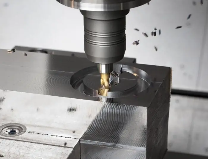
Cutting conditions for case hardened steels will depend on the hardness of the material. If it is less than 235 Brinnels, then the cutting speed will be appropriate - from 100 to 140 meters per minute. With a hardness of less than 285HB, the indicator drops - from 80 to 110 meters per minute. But at the same time, do not forget about the feed per tooth. In principle, you can not talk much about it, because it does not differ from what you have already seen in the previous paragraph. In the first case, it will have the same intervals as when machining general-purpose steel with a hardness of less than 190HB, and in the second case, the same intervals as when machining general-purpose steel with a hardness of less than 240HB. But at the same time, it cannot be said that the feed per tooth will be identical, because in the first case, the feed to the maximum tool diameter is not 0.1, as in the previous example, but 0.15. That is why the calculation of cutting data is such a complex task, which is best done according to all norms and in accordance with strict regulations.
Nitriding steels
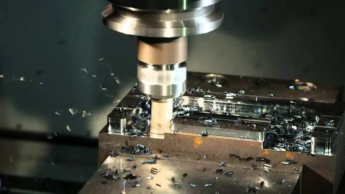
Calculation of cutting conditions when machining nitrided steels is no different from previous cases - only in this case the materials are slightly harder than the previous ones, so you should not be surprised that the cutting speed here will be from 90 to 125 meters in minute with less hard steel and 70 to 95 meters per minute with harder material. As for the feed per tooth, in the first case there is quite a standard step run - from0.008 to 0.08 millimeters, but if the metal has a large number of Brinell hardness units, this will mean that its supply will decrease, and noticeably. With a minimum tool diameter, it will be 0.006 mm, and with a maximum diameter of 0.06 mm. This is currently the lowest feed per tooth discussed in this article. The calculation of cutting conditions from this information is carried out quite usually according to the standard formula, which will be discussed at the end of the article.
Medium carbon steels
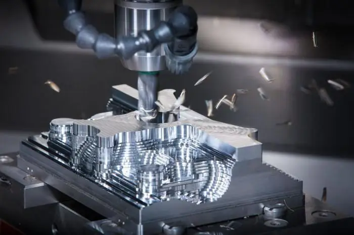
Medium carbon steels are very common, and most importantly - there are several different levels of their hardness. And, of course, each of them will have its own cutting speed. For example, the first two types of steel have the same rate if the cutter has no coating - 80 meters per minute. But with maximum coverage for the first type, the speed increases to 110 meters per second, and for the second - only up to 85 meters per second. But at the same time, there are two more types, the first with a hardness of less than 340HB, and the second - less than 385HB. Accordingly, the first cutting parameter will be from 50 to 70 m / min, and the second - from 35 to 50 m / min. Compared to the types you've seen before, this is pretty slow. Accordingly, for these types of steel, the feed per tooth is not too high - it is worth highlighting the last steel in terms of hardness, which, with a minimum tool diameter, has an incredibly low feed, only 0.005 mm. It should be noted right away that milling is considered here, and not cutting conditions forturning. As mentioned above, the formula used for the calculation, which you will read above. Turning cutting conditions are calculated using a slightly different formula, so you should not try to apply one calculation to all types of work.
Tool steels
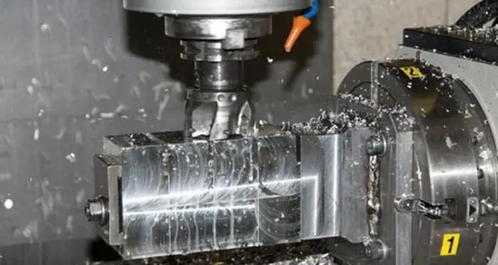
In terms of hardness, tool steels are divided into even more types than medium carbon ones, so cutting conditions when milling tool steel can be numerous. If we briefly talk about this particular steel, then there are five types of hardness: less than 230HB, less than 285HB, less than 340HB, less than 395HB and more than 395HB. Each of them has its own cutting speed: from 90 to 125 m/min, from 70 to 95 m/min, from 60 to 85 m/min, from 45 to 65 m/min and from 30 to 40 m/min, respectively. In fact, the name of this data you will be already halfway to filling in all the missing gaps in the calculation of the formula, which determines the cutting conditions during milling. In order for all variables to be replaced by numbers in the formula, you also need to know the diameter of the tool (and the feed per tooth data derived from it).
How to choose the mode?
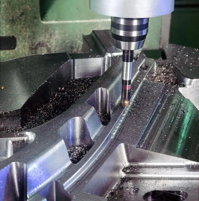
The choice of cutting modes is quite simple - each cutter has a switch that will allow you to control the speed of rotation of the cutting tool. With this little switch, you can set an approximate RPM value, and then your machine will work exactly at this level. Strictly speaking, this is the cutting mode, butsuch a simple process has a large number of calculations behind it, which will be discussed later. The fact is that the determination of the speed of rotation of the cutting tool of the cutter must be as accurate as possible, and rarely do you have enough time and material to select metal cutting modes at random. That is why there is a theory that must be used before practical application.
Cutting speed formula
It is very important to comply with the standards of cutting conditions, since the point here is not only that you will spend a lot of time, but even worse - a lot of material to select the desired mode blindly. It may also be unsafe. Therefore, it is best to be guided by theoretical knowledge in the first place. So, now you will learn the formula by which the mode for a particular metal is calculated. How it can be applied in practice will be described below. The formula itself assumes that the speed, expressed in meters per minute, is multiplied by a conversion factor of 1000, and the result is divided by the product of the number "pi" multiplied by the diameter of the cutter. These are all the cutting data you need to calculate the rotational speed of the cutter.
Simplified formula
There is no point in doing two multiplications when you know that pi is a digit without any variables. Initially, it is customary to reduce 1000 and 3.14 to get 318. 318 is multiplied by the speed, and then the result is divided by the diameter of the cutter. That's all, this formula is already much simpler than the previous one, and it is with its help thatcutting mode definition.
Calculation
In such material it is impossible to do without an example. Well, for example, we can take a general purpose steel with a hardness of less than 150HB and a cutter with a TI-NAMITE coating and a diameter of 10 millimeters. So, first you need to check the data that was described in the article above - with such indicators, the cutting speed will be 175 m / min, so you need to multiply 318 by 175, you get 55650. Now you need to divide this by the diameter of the cutter, that is, 10 - it turns out 5565. This is precisely the desired value. Now you need to set it on your machine, and if it is impossible to set such a value, then it is recommended to take a little less.
Foreign instrument catalog
If you use a domestic cutter, then most likely you can easily find the necessary data to determine the cutting mode. If you have a foreign sample, then you may have certain problems. That is why, when buying a foreign milling machine, it is extremely necessary to ask for a catalog with all the necessary explanations, which you can then use as a theoretical basis when working with the machine.
Special charts
Real salvations are graphs that are compiled for faster and more convenient determination of the cutting mode. What is such a graph? This is a set of straight lines of different colors that are between two axes - one of them shows the speed, that is, the value that you know, because you know what kind of material you are processing, andthe second is the number of revolutions per minute that your cutter will make, that is, in other words, its mode of operation. Why are the lines different colors? In case you haven't forgotten, the number of revolutions per minute of the cutter cannot be calculated only by cutting speed - you also need the diameter of the tool, and each color is responsible for its diameter.
How to use the chart?
All that is required of you is to find the diameter of your tool in the table and select the line of the desired color on the chart. Then you need to determine the speed and draw a straight line from the y-axis, that is, the axis on which the values \u200b\u200bof this parameter are indicated. From the intersection of your line with the line of your chosen color, you need to draw a straight line to the x-axis to find out the exact number of revolutions per minute.
Recommended:
Safety precautions for a welder during work: standards, rules and instructions
Welder is not an easy profession, but very necessary and in demand. However, we all know that this type of activity is not the safest. Today we will look at the safety precautions that professionals must follow in order to avoid accidents while working
Cutting speed for milling, turning and other types of mechanical processing of parts
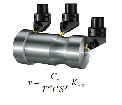
Calculation of cutting conditions is the most important step in the manufacture of any part. It is very important that the calculation itself be rational. This is due to the fact that for various mechanical operations it is necessary to individually select the cutting speed, spindle speed, feed rate, and also the depth of cut. A rational mode is one in which production costs will be minimal, and the quality of the resulting product will be as accurate as possible
Milling is Milling fixture and procedure description
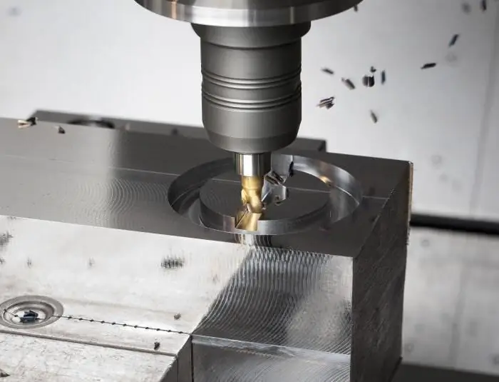
Milling is a surface treatment method based on the alternate operation of the teeth of the cutter. There is a huge variety of tools depending on their functional purpose, processed materials, characteristics of manufactured parts
Cutting mode for milling. Types of cutters, calculation of cutting speed
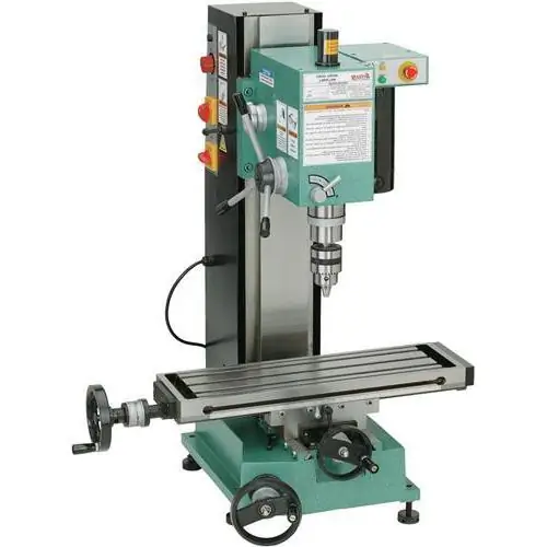
One of the ways to finish materials is milling. It is used for processing metal and non-metal workpieces. The workflow is controlled by cutting data
Metal cutting machine. Plasma metal cutting machine
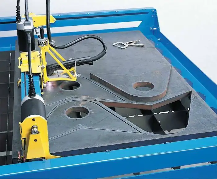
The article is devoted to the apparatus for cutting metal. The technology of plasma cutting, as well as the device and features of the equipment are considered

