2026 Author: Howard Calhoun | calhoun@techconfronts.com. Last modified: 2025-01-24 13:10:43
In instrumentation and electronics in general, printed circuit boards play a crucial role as carriers of electrical interconnections. The quality of the device and its basic performance depends on this function. Modern methods of manufacturing printed circuit boards are guided by the possibility of reliable integration of the element base with a high layout density, which increases the performance of the manufactured equipment.
PCB Overview

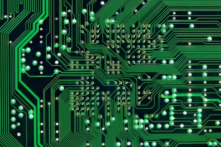
We are talking about products based on a flat insulating base, the design of which has grooves, holes, cutouts and conductive circuits. The latter are used for switching electrical devices, some of which are not included in the board device as such, and the other part is placed on it as local functional nodes. It is important to emphasize that the placementof the aforementioned structural elements, conductors and working parts are initially presented in the product design as a well-thought-out electrical circuit. For the possibility of future soldering of new elements, metallized coatings are provided. Previously, copper deposition technology was used to form such coatings. This is a chemical operation that many manufacturers have abandoned today due to the use of harmful chemicals like formaldehyde. It has been replaced by more environmentally friendly methods of manufacturing printed circuit boards with direct metallization. The advantages of this approach include the possibility of high-quality processing of thick and double-sided boards.
Materials for making
Among the main consumables are dielectrics (foiled or non-foiled), metal and ceramic blanks for the base of the board, fiberglass insulating gaskets, etc. The key role in ensuring the necessary performance properties of the product is played not only by the basic structural materials for basics, how many outdoor coatings. The applied method of manufacturing printed circuit boards, in particular, determines the requirements for bonding materials for gaskets and adhesive coatings to improve adhesion of surfaces. So, epoxy impregnations are widely used for gluing, and polymeric varnish compositions and films are used to protect against external influences. Paper, fiberglass and fiberglass are used as fillers for dielectrics. In this case, epoxyphenolic, phenolic andepoxy resins.

Single-sided printed circuit board technology
This manufacturing technique is one of the most common, as it requires minimal resource investment and is characterized by a relatively low level of complexity. For this reason, it is widely used in various industries, where, in principle, it is possible to organize the work of automated conveyor lines for printing and etching. Typical operations of the single-sided printed circuit board manufacturing method include the following:
- Preparing the base. The blank sheet is cut to the desired format by mechanical cutting or punching.
- The formed package with blanks is fed to the input of the production line of the conveyor.
- Cleaning blanks. Usually performed by mechanical deoxidation.
- Printing paints. Stencil technology is used to apply technological and marking symbols that are resistant to etching and cured under the influence of ultraviolet radiation.
- Copper foil etching.
- Removing the protective layer from the paint.
In this way, low-functional, but cheap boards are obtained. As a consumable raw material, a paper base is usually used - getinaks. If the emphasis is on the mechanical strength of the product, then a combination of paper and glass in the form of an improved CEM-1 grade getinax can also be used.

Subtractive manufacturing method
Contours of conductorsaccording to this technique are formed as a result of etching copper foil on the base of a protective image in a metal resist or photoresist. There are various options for implementing subtractive technology, the most common of which involves the use of dry film photoresist. Therefore, this approach is also called the photoresistive method of manufacturing printed circuit boards, which has its pros and cons. The method is quite simple and in many respects universal, but boards of low functionality are also obtained at the output of the conveyor. The technological process is as follows:
- The foil dielectric is being prepared.
- As a result of the layering, exposure and development operations, a protective pattern is formed in the photoresist.
- Copper foil etching process.
- Removing the protective pattern in the photoresist.
With the help of photolithography and photoresist, a protective mask is created on the foil in the form of a pattern of conductors. After that, etching is performed on the exposed areas of the copper surface, and the film photoresist is removed.
In an alternative version of the subtractive method of manufacturing printed circuit boards, a photoresist is layered on a foil dielectric, which was previously machined to create holes and pre-metallized with a thickness of up to 6-7 microns. In areas not protected by photoresist, etching is performed sequentially.

Additive PCB Forming
ThroughThis method can form patterns with conductors and gaps in the range of 50 to 100 µm in width and 30 to 50 µm in thickness. An electrochemical approach is applied with galvanic selective deposition and spot pressing of insulating elements. The fundamental difference between this method and the subtractive one is that metal conductors are applied, not etched. But additive manufacturing methods for printed circuit boards have their own differences. In particular, they are divided into purely chemical and galvanic methods. The most commonly used chemical method. In this case, the formation of conductive circuits in the active areas provides for the chemical reduction of metal ions. The speed of this process is about 3 µm/h.
Positive combined manufacturing method
This method is also called semi-additive. In the work, foil dielectrics are used, but of a smaller thickness. For example, foils from 5 to 18 microns can be used. Further, the formation of the conductor pattern is carried out according to the same models, but mainly with galvanic copper deposition. The key difference between the method can be called the use of photomasks. They are used in the combined positive method of manufacturing printed circuit boards at the stage of pre-metallization with a thickness of up to 6 microns. This is a so-called galvanic tightening procedure, in which the photoresistive element is applied and exposed through a photomask.

Advantages of the combined methodPCB manufacturing
This technology allows you to form elements of the picture with increased accuracy. For example, with a positive method of manufacturing printed circuit boards on a foil consumable with a thickness of up to 10 microns, it is possible to obtain a resolution of conductors up to 75 microns. Along with the high quality of the dielectric circuits, a more effective surface isolation with good adhesiveness of the printed substrate is also ensured.
Pair pressing method
The technology is based on the method of making interlayer contacts using metallized holes. In the process of forming the pattern of conductors, sequential preparation of segments of the future base is used. At this stage, a semi-additive method for manufacturing printed circuit boards is used, after which a multilayer package is assembled from the prepared cores. Between the segments there is a special lining made of fiberglass treated with epoxy resins. This composition can flow out when squeezed, filling the metallized holes and protecting the electroplated coating from chemical attack during further technological operations.

PCB layering method
Another way, which is based on the use of several segments of printed substrates to form a complex functional structure. The essence of the method lies in the successive imposition of layers of insulation with conductors. At the same time, it is necessary to ensure reliable contacts between adjacent layers, which is ensuredgalvanic copper build-up in areas with insulating holes. Among the advantages of this method of manufacturing multilayer printed circuit boards, one can note the high density of the layout of functional elements with the possibility of compact assembly in the future. Moreover, these qualities are preserved on all layers of the structure. But there are also disadvantages of this method, the main of which is the mechanical pressure on the previous layers when applying the next one. For this reason, the technology is limited in the maximum allowable number of applied layers - up to 12.
Conclusion

As the requirements for the technical and operational characteristics of modern electronics increase, the technological potential in the tools of the manufacturers themselves inevitably increases. The platform for the implementation of new ideas is often just a printed circuit board. The combined method of manufacturing this element shows the level of modern manufacturing capabilities, thanks to which developers can produce ultra-complex radio components with a unique configuration. Another thing is that the concept of layer-by-layer growth does not always justify itself in practice in applications in the simplest radio engineering, so so far only a few companies have switched to serial production of such boards. Moreover, the demand for simple circuits with a one-sided design and the use of cheap consumables remains.
Recommended:
Motor oil production: characteristics, technology and manufacturing process
The production of motor oil, like any other, is not complete without raw materials - the substance from which the final product is obtained. Mineral oil is made from petroleum. But before it gets to the lubricants plant, it needs to go through a series of cleanings at oil refineries
Styrofoam production business plan: step-by-step opening steps, manufacturing technology, calculation of income and expenses
Polyfoam can be attributed to one of the most widely used building materials. The demand for it is quite high, as there is a development of sales markets, which, with a competent marketing approach, can provide stable profits for a long period of time. In this article, we will consider in detail the business plan for the production of foam plastic
Slaughter of cattle at meat processing plants: rules, technology, methods and methods
Providing the consumer basket with meat products directly depends on the slaughter and processing of cattle. Delicious beef and veal dishes are largely the merit of livestock breeders who know how to properly slaughter bulls and cows. There are various technologies, methods and methods for slaughtering cattle, which make it possible to obtain high quality meat products
Gas production. Gas production methods. Gas production in Russia
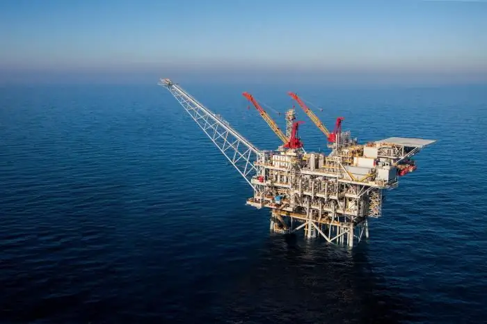
Natural gas is formed by mixing various gases in the earth's crust. In most cases, the depth of occurrence ranges from several hundred meters to a couple of kilometers. It is worth noting that gas can form at high temperatures and pressures. In this case, there is no access of oxygen to the place. To date, gas production has been implemented in several ways, each of which we will consider in this article. But let's talk about everything in order
Carpet production: technology and manufacturing features
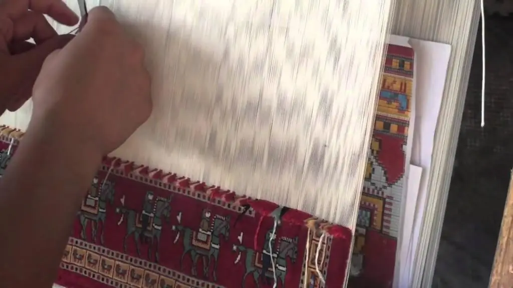
Any carpet production begins with the selection of raw materials. And if earlier the choice of materials was limited to wool and silk, today you can find a woven fabric from both natural fibers and their synthetic counterparts

