2026 Author: Howard Calhoun | [email protected]. Last modified: 2025-01-24 13:10:41
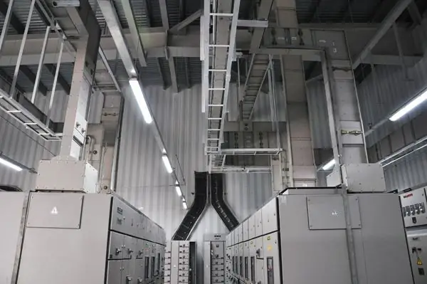
Power supply wiring in manufacturing plants and construction sites needs additional protection. Conventional insulation does not always cope with these tasks, so special circuits are used that also perform the functions of distribution and optimized connection. A typical execution of such wiring is a trunk bus duct containing one or more power lines.
Device overview

The design of the busbar is a rigid channel for laying cables operating under voltage up to 1 kV. The frequency of alternating current in the network can be 50-60 Hz, and the power can be up to 250 A. The key characteristic is the resistance of the busbar trunking case, since it is designed to protect the line from mechanical, thermal, moisture and chemical influences. To indicate the protective properties, a classification by code is used. IP. In particular, the IP68 marked trunk duct can be used both in residential buildings and in substations and industrial workshops where extreme temperature loads are noted. The cast insulation also protects the circuit from pressure, water, dust and electromechanical interference. But besides the protective function, the bus duct also has an ergonomic task, which is to simplify the process of connecting equipment to the power grid.
Classification of busbars

As different as the conditions for the use of insulating enclosures can be, the types of busbars are just as varied. The most common include the following features of classifications:
- The degree of enclosure closure. There are both fully sealed and open structures. It directly depends on the communication requirements of the device and the operating environment.
- Mobility. Allocate stationary and portable circuits. The choice of the main bus duct according to this criterion also depends on the nature of the cable application in specific conditions. Stationary housings are more often used in enterprises with fixed fixed points and power supply channels. In turn, portable bus ducts are used at facilities with aggressive environments without a permanent electrical infrastructure.
- Material of production. Basically, metal is used that has been treated to acquire anti-corrosion properties. It can also be anodized aluminum alloys (they are lightweight andcompactness), and stainless steel (heavy but durable construction with a high degree of protection).
Types of busbar sections

An insulated channel of this kind does not at all belong to linear shafts of the same type, which change only in the parameters of the section and dimensions. A full-fledged busbar has butt, rotary and other complex elements, represented by sections of one type or another. The standard varieties of busbar trunking segments include the following:
- Connecting section. It is used for switching with the control panel and connecting the channel to the busbars of the electrical panel.
- End feed section. Introduced into the network to regulate the energy in the busbar by taking it through a flexible cable.
- Connection corner section. It can be used to introduce the bus into the network on difficult turning sections, where it is impossible to use typical construction segments.
- Passable segments. An extensive group of prefabricated tire elements that are used in transitional and nodal technological areas with special requirements. For example, it can be passages through floors and walls, areas with increased fire danger, etc.
Busbar Trunk Structures

A distinctive feature of such devices is the ability to withstand high currents in the range from 1600 to 4000 A. The standard configuration of the shaft allows you to install two power supplies for every 6 m of the maincoupler. The most popular design format is the ShMA type. This device contains three tires, one of which is represented by a zero contour placed outside the body in the form of two aluminum corners. The basis of the main busbar SHMA is made up of straight sections with a length of 75 to 350 cm. Tee, angle, branch and a wide group of connecting elements can act as additional functional segments. Flexible sections are used to avoid obstacles, which also allow you to change the phase sequence.
Busbar Distribution Structures
The main share of such devices is carried out according to the ShRA system with a current strength of up to 630 A. The primary task of distribution routes is the functional network placement of circuits and branches of cable lines. Therefore, the current strength is low, but extensive wiring layout options are provided. Both distribution and main bus ducts provide for the integration of several points for the input of power supply sources. But if the maximum number of the main canal rarely exceeds three, then the SRA system allows you to connect up to six power receivers on a three-meter section. Four-bar distribution structures are also used, in which one zero and three phase circuits are provided.

Lighting busbars
Special channel to create a powerful and functional lighting system. In its arrangement, tires of 25 A are used, and the phase may be different - and at 380,and 220 V. Single-phase systems are also used in industrial conditions, when there is no need for a high load for low-cost consumers. It is possible to make a branch from the main busbar at 0.4 kV along the SCO line, and then group point decouplings on single-phase plug connections for each lighting device after 5-10 m. The devices are suspended by means of clamps with hooks and connected to the plug. The step of fastening the structure on average varies from 2 to 3 m.
Busbar installation
The channel is mounted using metal profiles and a system of fixing hardware. Initially, a wiring diagram is drawn up indicating the contours of the gasket and the installation points of the busbar trunking. Further, the premises where the route will pass are being prepared. In particular, cuts and holes are formed along the walls and floor, through which fastening will be carried out. The standard installation instructions for trunk bus ducts require that the installation be carried out in conditions of readiness of the premises for construction and repair operations with full protection of the channel elements from contamination and mechanical damage.

At the first stage, linings from U-shaped metal profiles are mounted. They are attached to the floor with screws, screws or dowels. Further, the body of the product is integrated into the existing groove, after which the closing U-shaped profile follows, which is joined to the supporting similar elements by means of an anchor bolt and a connecting stud.
Using the device
Bas a protective and mounting electrical accessories, the busbar can be used not only at manufacturing enterprises in assembly shops with conveyor lines, but also in administrative, public and residential buildings. The wide scope of such devices is due to the high reliability and degree of protection, which allows you to protect the cable line from various kinds of damage. Power installation of the main bus duct can be carried out in almost any planning conditions, including through windows, openings and ceilings. This nuance also contributes to the spread of fittings, complemented by sections of different sizes and formats.
Conclusion

In choosing the right busbar trunking, it is important to take into account not only the protection requirements of the main current-carrying line, but also the logistical factors of installation. The fact is that cable routes serve to power specific consumers, but the position of the latter during the operation of the facility may change. So that such rearrangements do not force the re-equipment of the electrical infrastructure, the configuration of the main bus duct is calculated in advance from the point of view of its interaction with the equipment being serviced. Of course, do not forget the risks of possible emergencies. They are laid at the stage of project creation - for example, a typical bus duct must withstand an overload of up to 10% above the nominal network performance for 2 hours / day. Microclimatic impact factors, electromagnetic interference, etc. are calculated separately.
Recommended:
Glass furnace: types, device, specifications and practical application

Today, people actively use glass for a variety of purposes. The glassmaking process itself is the melting of raw materials or charge. Glass melting furnaces are used to melt the material. They come in different types and are classified according to several criteria
Turbocharger device: description, principle of operation, main elements

Today, people are actively using internal combustion engines. Naturally, its main use falls on a motor vehicle. The turbocharger device for internal combustion engines is very important, and therefore it is worth knowing, especially for those who have a personal car
Main types and types of business plans, their classification, structure and application in practice

Each business plan is unique, because it is developed for certain specific conditions. But you need to familiarize yourself with the features of various types of business plans in order to understand their key features. Experts recommend doing this before compiling your own similar document
Viewing well: description, device, types and features

There are many elements in the sewerage system that are designed to ensure the smooth operation of the network. The inspection well acts as one of the main structures, with the help of which specialists check the performance and clean the sewer
Two-component polyurethane sealant: definition, creation, types and types, characteristics, properties and nuances of application

With long-term and high-quality sealing of seams and cracks, polyurethane two-component sealants have found their wide distribution. They have high deformation and elastic properties, therefore, they can be used as butt sealants in the field of repair and housing construction

