2026 Author: Howard Calhoun | [email protected]. Last modified: 2025-01-24 13:10:45
Oil and gas refineries are required to be provided with means to prevent technological leaks into the open air. For this, special devices are used that are connected to safety valves and production plants. To burn excess gases and vapors, flare systems are used, which are connected to technological waste disposal channels at energy enterprises.
Treatment of flare installations
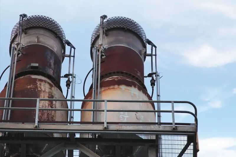
Equipment of this type is included in the general technological infrastructure serving the processes of production, storage and transportation of oil and gas mixtures. The system includes a network of pipelines, flare stacks with tips, burners, gates, as well as automated control and monitoring tools. In addition, the installation of a flare system is not complete without devices that ensure safefuel combustion. The number of burn points depends on the design volumes that a particular infrastructure can in principle serve. This parameter is closely interconnected with other operational properties of the object. For example, if less than three burner shafts are used, then the design of the installation must include a wind shield in order to maintain the flame.
The burners are supplied with channels for supplying the gas-air mixture, and the circuit with the ignition mixture is connected to the ignition device. To normalize the combustion process at different times of the year, installations are provided for the regulation of individual temperature and humidity conditions. In cold weather, for example, to eliminate the possibility of freezing in the pipes for supplying fuel mixtures, pipeline heaters can be connected. There are also special requirements for gas. Flare systems operate stably only if the mixtures being serviced are pre-drained - in any case, this applies to operation in winter.
System functions
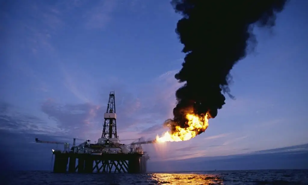
The primary tasks of this type of flares include the burning of associated gas mixtures in order to prevent their accidental release into the atmosphere. This applies not only to gases as such, but also to various process vapors, which also pose a danger to the environment. At the same time, specific tasks may differ for different torches. From the point of view of functional orientation, two basic types of installations can be distinguished:
- General. The most common flare systems,that are used in production facilities. They include in their infrastructure many additional technological facilities such as a separator, water seal, fire arrester and collector.
- Separate. Such systems find their place in the existing common flare infrastructure. This combination model is used when the main gas flaring system is unable to fully service the vents.
There is also a special group of special systems. The key feature of this type of flares is the ability to work with process mixtures that cannot be disposed of by common and separate flares. These waste products include:
- Products that decompose when they release heat.
- Substances that react with other waste products.
- Highly toxic and corrosive mixtures.
- Gas-air mixtures, including mechanical impurities.
Horizontal and vertical systems
Depending on the structural conditions at the enterprise, the operation of horizontal or vertical flare installations can be organized. Structures of the first type are mainly involved in the implementation of blowing wells, plumes and production lines. Such systems are characterized by the use of burner shafts which are capable of providing sufficient air injection to enable smokeless combustion. On gas wells, according to the instructions, horizontal burners should be used.structures that will ensure the disposal of products containing liquid plugs and mechanical impurities. At the same time, to maintain the safety of horizontal flare systems, a moderate heat flux density of up to 1.4 kW/m2 should be maintained. Additional means of minimizing thermal exposure in the form of protective screens may also be used to protect personnel maintaining the operation of such systems.
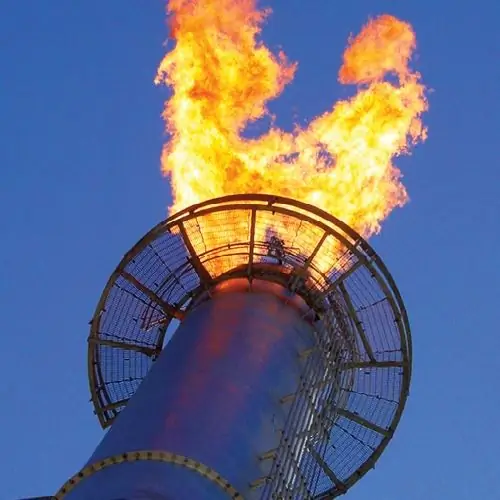
Vertical units are equipped with pumps and devices for condensate removal. The functional basis of the design is formed by a head, which is a metal device for regulating the delivery of a gas mixture. In some system models, they also prevent the passage of the flame to the barrel of the working installation. At the end of the vertical shaft, burners with a windshield are placed. Ignition can be installed both in the structure of the head and as part of the trunk. Ignition pipelines are supplied to the burners in a separate order. The flare system technical manual requires that flame control be independent of supervisory control by means of ionization probes, thermocouples, acoustic or optical sensors.
Features of closed flares
This type of gas flare is designed to burn technological combustible mixtures near the earth's surface. Closed installations include a combustion chamber, the surfaces of which are treated with a protective lining. Unlike a burner, thisequipment has a higher productivity, but it also has increased requirements in terms of providing protective properties. As noted in the flare safety manual, the chambers of enclosed installations must be enclosed to prevent uncontrolled air entry. The torch must ensure the complete utilization of incoming gases in the absence of a visible flame. The air flow necessary to maintain combustion, together with the return of flue gases, is organized through natural or forced draft with the possibility of controlling the throughput.
The burner assembly for closed flare systems is selected with the expectation of ensuring stable and sustainable combustion. The reliability requirements in this case are higher than in the case of conventional open-type installations. According to the regulations, combustion with impulses and resonant oscillations of the flame must be excluded. This is guaranteed by a uniform flow of oxygen into the combustion chamber.
Requirements for flare facilities
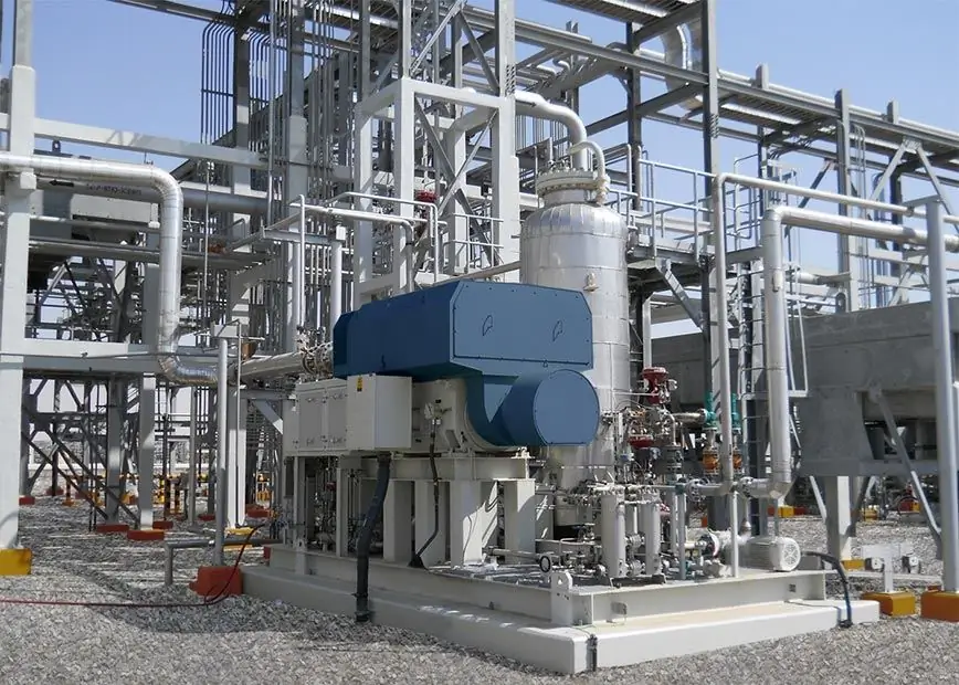
Associated gas utilization systems are located taking into account the wind rose and the technical capabilities of installing pipeline lines with fences and outlet channels for burners. Regardless of the type of installation, the standard distances between flare stacks, buildings, engineering structures, warehouses and electrical substations must be maintained. Specific distances for direct placement of burners on the territory of the enterpriseare calculated on the basis of the planned heat flux density of the flare system. The rules also indicate the need to create conditions for the repair and maintenance of shafts during the operation of neighboring installations. In this regard, it is recommended that personnel ladders be located on the side of the shaft opposite the location of the adjacent burner. Materials for the manufacture of structures that are in the zone of activity of heat flows must have a fire-resistant structure or special heat-resistant coatings.
Requirements for flare discharge technology
Organization of the work of gas flares is largely determined by the requirements of the general technological process at the enterprise. Nevertheless, the stage of interaction between gas sources and burners is also regulated by regulatory documents. During the design phase of the system, the vent parameters must be determined, in particular pressure, temperature, density and flow rates. Based on the calculations made, a scheme for discharge into the flare system of the most suitable type is developed. Discharge sources should also be able to supply prophylactic gases rather than target workers, which include inert and purge mixtures. Conversely, when dumping, compositions including acetylene, hydrogen, carbon oxides and fast-burning components should not be sent. The composition of the technological combustion plant may include separators responsible for the separation of solid particles and liquid droplets in vapor and gas mixtures. These substances and components are processed in separateflare devices.
Rules for the operation of flare systems
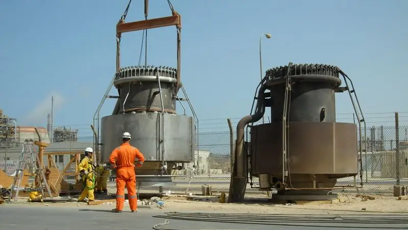
Before each launch of the installation, it is necessary to purge the barrel with inert gas mixtures in order to remove oxygen. Further airing of the flare channels is prevented by control valves when the burners are switched off. The level of oxygen content is checked by taking samples with further analysis. During combustion, it is recommended to set the burner speed to the following modes:
- For a cap with a gas seal - not less than 0.05 m/s.
- If there is no gas seal - not less than 0.9 m/s.
- When supplying inert gas - not less than 0.7 m/s.
Also, when operating flare systems not equipped with shutters, the purge mixtures must have a density of more than 0.7 kg/m3.
Before stopping the discharge of process gas or heated vapors, it is recommended to pre-connect channels with the direction of inert mixtures, which will prevent the formation of a vacuum during condensation or cooling. Before performing maintenance or repair work, pipelines are disconnected from the flare installation to prevent gas mixtures from being discharged and ignition. Residues of combustible gases, as well as flue mixtures, must be completely removed from the channels. Prior to technical work, the trunks are purged with nitrogen and, if necessary, steamed.
Flame controls
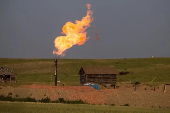
Ignition is carried out by the so-called runningfire or electric spark system on the pilot burner. Further, combustion control is carried out by acoustic sensors and a thermoelectric converter. For control, an autonomous ignition and flame control unit is also used, which must be located in a separate cabinet with heating. Operating modes with automatic connection involve work according to specified algorithms with signal transmission to the operator's console. To activate emergency modes or automatically connect the operator's console, certain signals are set. For example, the manual for flare systems in the event of a failure to successfully ignite a flame after 10 cycles indicates the need to automatically trigger an alarm. If the sensors for detecting signs of fire do not work, then the remote control panel is connected to the work. With it, the staff already takes over the control functions through the interface to control the ignition of the flare plant.
Flare Safety Guide
Regulatory requirements establish the following safety rules for the operation of gas flares and related technological systems:
- When organizing gas discharges from the flare stack into the atmosphere, the permissible levels of harmful substances must be observed.
- In order to prevent the formation of an explosive mixture, the rules for the safe operation of flare systems prescribe regular cleaning of the gas mixture discharge circuits.
- It is forbidden to send to the combustion chambers of substances,which may cause an explosion. Such substances in oil and gas enterprises, in particular, include chemical oxidizing agents and reducing agents.
- The territory for the location of process units operating flare equipment must be fenced.
- Only persons who have the appropriate qualifications and have been verified in terms of industrial safety should be allowed to service gas flares.
Conclusion
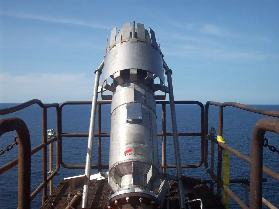
Technologies for combustion of working gases at modern enterprises reach a fairly high level in terms of reliability and safety. This is largely due to the use of innovative means of control and management of complex combustion processes of combustible mixtures. For example, the safe operation of flare systems at the current level is impossible without the use of automated control elements with the connection of sensors and industrial controllers. This does not exclude the manual control mode - at least it is provided as an option. Operator consoles still bear a great responsibility in the processes of regulating the operation of flare installations, monitoring their parameters and diagnostic indicators. At the same time, the designs of burners with barrels forming a flare infrastructure are also being improved. Manufacturers are using ever more reliable materials with heat-resistant coatings and high mechanical resistance. All this makes it possible to optimize the overall work processes of oil and gas enterprises at the proper level of safety and environmental protection.
Recommended:
Hydraulic system: calculation, scheme, device. Types of hydraulic systems. Repair. Hydraulic and pneumatic systems

The hydraulic system is a special device that works on the principle of a liquid lever. Such units are used in the braking systems of cars, in loading and unloading, agricultural machinery and even in the aircraft industry
Aspiration systems: calculation, installation. Production of aspiration systems
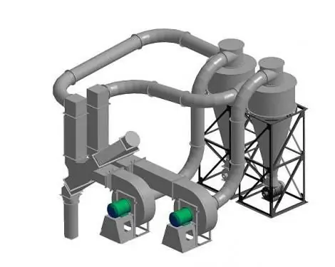
Aspiration systems are systems that are designed to purify the air. The use of these installations is mandatory at all industrial enterprises that are characterized by harmful emissions into the atmosphere
Visa and Mastercard systems in Russia. Description of Visa and Mastercard payment systems

Payment system - a commonality of methods and tools used for money transfers, settlements and regulation of debt obligations between participants in economic turnover. In many countries, they differ significantly from each other due to the diverse provisions in the levels of economic development and the characteristics of banking legislation
Flame control sensors - features, device and principle of operation
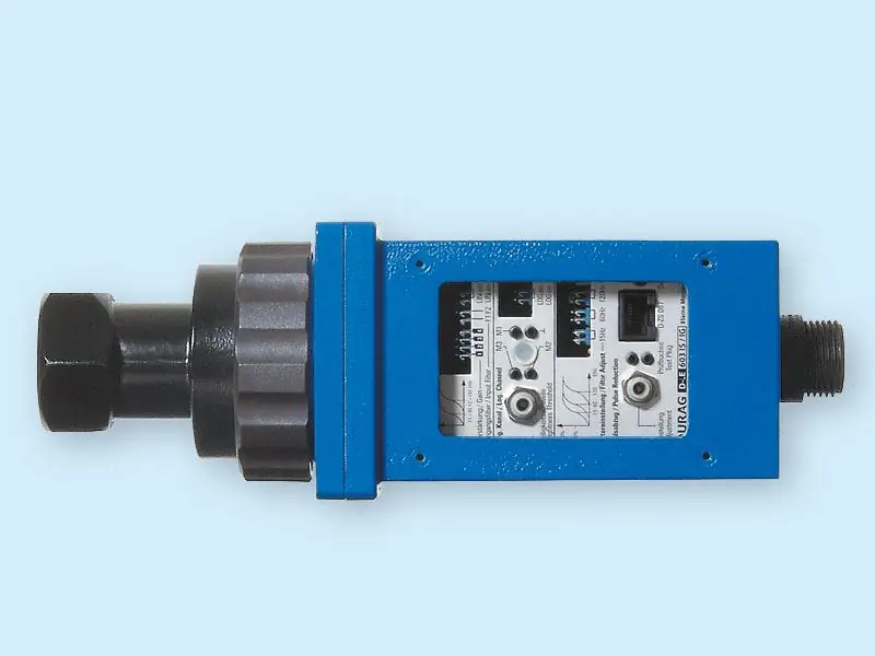
Today, people actively use fire for their own purposes. However, it is very dangerous, and therefore, when working with it, it is necessary to put safety in the first place. On an industrial scale, this role is played by a flame control sensor
Corporate systems - enterprise management systems. Basic Models

The article discusses the concepts of "corporate enterprise management systems" and "corporate project management system". In addition, the basic models of CPMS are described

