2026 Author: Howard Calhoun | [email protected]. Last modified: 2025-01-24 13:10:26
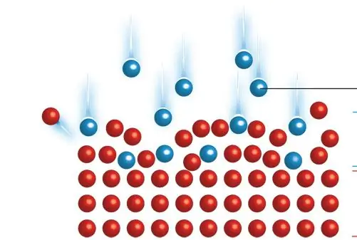
Ion implantation is a low-temperature process by which the components of a single element are accelerated into the solid surface of a wafer, thereby changing its physical, chemical or electrical properties. This method is used in the production of semiconductor devices and in metal finishing, as well as in materials science research. Components can change the elemental composition of the plate if they stop and remain in it. Ion implantation also causes chemical and physical changes when atoms collide with a target at high energy. The crystalline structure of the plate can be damaged or even destroyed by energy cascades of collisions, and particles of sufficiently high energy (10 MeV) can cause nuclear transmutation.
General principle of ion implantation

Equipment usually consists of a source where atoms of the desired element are formed, an accelerator where they are electrostatically accelerated to a highenergy, and target chambers where they collide with the target, which is the material. Thus, this process is a special case of particle emission. Each ion is usually a single atom or molecule, and thus the actual amount of material implanted into the target is the time integral of the ion current. This number is called the dose. The currents supplied by implants are usually small (microamps) and therefore the amount that can be implanted in a reasonable amount of time is small. Therefore, ion implantation is used in cases where the number of chemical changes required is small.
Typical ion energies range from 10 to 500 keV (1600 to 80000 aJ). Ion implantation can be used at low energies in the range of 1 to 10 keV (160 to 1600 aJ), but the penetration is only a few nanometers or less. Power below this results in very little damage to the target and falls under the designation of ion beam deposition. And higher energies can also be used: accelerators capable of 5 MeV (800,000 aJ) are common. However, there is often a lot of structural damage to the target, and because the depth distribution is wide (Bragg peak), the net change in composition at any point on the target will be small.
The energy of the ions, as well as different types of atoms and the composition of the target, determine the depth of penetration of particles into a solid. A monoenergetic ion beam usually has a wide depth distribution. The average penetration is called the range. ATunder typical conditions it will be between 10 nanometers and 1 micrometer. Thus, low energy ion implantation is particularly useful in cases where it is desired that the chemical or structural change be near the target surface. Particles gradually lose their energy as they pass through a solid, both from random collisions with target atoms (which cause abrupt energy transfers) and from slight deceleration from the overlap of electron orbitals, which is a continuous process. The energy loss of ions in a target is called stalling and can be modeled using the ion implantation method of the binary collision approximation.
Accelerator systems are generally classified into medium current, high current, high energy, and very significant dose.
All varieties of ion implantation beam designs contain certain common groups of functional components. Consider examples. The first physical and physico-chemical foundations of ion implantation include a device known as a source for generating particles. This device is closely associated with biased electrodes for extracting atoms into the beam line and most often with some means of selecting specific modes for transport to the main section of the accelerator. The selection of "mass" is often accompanied by the passage of the extracted ion beam through a region of magnetic field with an exit path limited by blocking holes or "slots" that allow only ions with a certain value of the product of mass and velocity. If the target surface is larger than the ion beam diameter andif the implanted dose is more evenly distributed over it, then some combination of beam scanning and plate movement is used. Finally, the target is connected to some way of collecting the accumulated charge of the implanted ions so that the delivered dose can be measured continuously and the process stopped at the desired level.
Application in semiconductor manufacturing
Doping with boron, phosphorus or arsenic is a common application of this process. In ion implantation of semiconductors, each dopant atom can create a charge carrier after annealing. You can build a hole for a p-type dopant and an n-type electron. This changes the conductivity of the semiconductor in its vicinity. The technique is used, for example, to adjust the threshold of a MOSFET.
Ion implantation was developed as a method of obtaining a pn junction in photovoltaic devices in the late 1970s and early 1980s, along with the use of a pulsed electron beam for rapid annealing, although it has not been commercialized to date.
Silicon on insulator

One of the well-known methods for producing this material on insulator (SOI) substrates from conventional silicon substrates is the SIMOX (separation by oxygen implantation) process, in which high-dose air is converted into silicon oxide through a high-temperature annealing process.
Mesotaxy
This is the term for growth crystallographicallycoinciding phase under the surface of the main crystal. In this process, ions are implanted at a sufficiently high energy and dose into the material to create a second phase layer, and the temperature is controlled so that the target structure is not destroyed. The crystal orientation of the layer can be designed to suit the purpose, even if the exact lattice constant can be very different. For example, after implanting nickel ions into a silicon wafer, a layer of silicide can be grown in which the crystal orientation matches those of silicon.
Metal Finish Application

Nitrogen or other ions can be implanted into a tool steel target (such as a drill). The structural change induces surface compression in the material, which prevents crack propagation and thus makes it more resistant to fracture.
Surface finish

In some applications, for example for prostheses such as artificial joints, it is desirable to have a target that is highly resistant to both chemical corrosion and wear due to friction. Ion implantation is used to design the surfaces of such devices for more reliable performance. As with tool steels, target modification caused by ion implantation includes both surface compression to prevent crack propagation and alloying to make it more chemically resistant to corrosion.
Otherapplications

Implantation can be used to achieve mixing of ion beams, that is, blending of atoms of different elements at the interface. This can be useful for achieving graduated surfaces or enhancing adhesion between layers of immiscible materials.
Formation of nanoparticles
Ion implantation can be used to induce nanoscale materials in oxides such as sapphire and silicon dioxide. Atoms can be formed as a result of precipitation or the formation of mixed substances that contain both an ion-implanted element and a substrate.
Typical ion beam energies used to obtain nanoparticles are in the range from 50 to 150 keV, and the ion fluence is from 10-16 to 10-18 kV. see A wide variety of materials can be formed with sizes from 1 nm to 20 nm and with compositions that can contain implanted particles, combinations that consist solely of a cation bound to the substrate.
Dielectric-based materials such as sapphire, which contain dispersed nanoparticles of metal ion implantation, are promising materials for optoelectronics and nonlinear optics.
Problems
Each individual ion produces many point defects in the target crystal upon impact or interstitial. Vacancies are lattice points not occupied by an atom: in this case, the ion collides with the target atom, which leads to the transfer of a significant amount of energy to it, so that it leaves itsplot. This target object itself becomes a projectile in a solid body and can cause successive collisions. Interstices occur when such particles stop in a solid but find no free space in the lattice to live in. These point defects during ion implantation can migrate and cluster with each other, leading to the formation of dislocation loops and other problems.
Amorphization
The amount of crystallographic damage may be sufficient to completely transition the target surface, that is, it must become an amorphous solid. In some cases, complete amorphization of the target is preferable to a crystal with a high degree of defectiveness: such a film can re-grow at a lower temperature than is required for annealing a severely damaged crystal. Amorphization of the substrate can occur as a result of beam changes. For example, when implanting yttrium ions into sapphire at a beam energy of 150 keV up to a fluence of 510-16 Y+/sq. cm, a vitreous layer approximately 110 nm thick is formed, measured from the outer surface.
Spray

Some of the collision events cause atoms to be ejected from the surface, and thus ion implantation will slowly etch away the surface. The effect is noticeable only for very large doses.
Ion channel

If a crystallographic structure is applied to the target, especially in semiconductor substrates where it is moreopen, then specific directions stop much less than others. The result is that the range of an ion can be much larger if it moves exactly along a certain path, such as in silicon and other diamond cubic materials. This effect is called ion channeling and, like all similar effects, is highly non-linear, with small deviations from ideal orientation resulting in significant differences in implantation depth. For this reason, most runs a few degrees off-axis, where tiny alignment errors will have more predictable effects.
Recommended:
Indicators without delay and redrawing: types, principle of operation, pros and cons of application, expert advice

There is a wide variety of different tools in trading: graphical constructions, technical indicators, automated programs, trading signals and much more. To successfully apply them in trading, you need to understand how they work. Indicators without delay and redrawing are especially popular with traders
Thermal imaging control of electrical equipment: concept, principle of operation, types and classification of thermal imagers, features of application and verification

Thermal imaging control of electrical equipment is an effective way to identify defects in power equipment that are detected without shutting down the electrical installation. In places of poor contact, the temperature rises, which is the basis of the methodology
Drainage of the soil: concept, purpose, methods and methods of work

Irrigation and drainage of soils are very important measures aimed at improving the conditions for normal growth and development of plants. Most novice farmers do not have questions about high-quality irrigation, but not everyone knows what drainage is. So why do you need to drain the soil, in what cases to do it, how to properly carry out this procedure and what it will give
Low pressure heaters: definition, principle of operation, technical characteristics, classification, design, operation features, application in industry

Low pressure heaters (LPH) are currently used quite actively. There are two main types that are produced by different assembly plants. Naturally, they also differ in their performance characteristics
General purpose engines: device, principle of operation, application, photo

Automotive equipment is mainly equipped with standardized internal combustion engines (ICEs), the design of which is focused on placement in the engine compartment. However, there is a great demand for power units of this kind in the garden equipment segments, from manufacturers of snowplows, snowmobiles, etc. Moreover, the requirements for integration and operational parameters in such cases differ sharply from automotive standards

