2026 Author: Howard Calhoun | calhoun@techconfronts.com. Last modified: 2025-06-01 07:12:56
Delayed coking units are the most common hardware solution for heavy oil refining. Their device includes 2 main modules - reactor, where the raw material is heated and coked, and mechanical processing. The design of plants is carried out in stages and includes the calculation and selection of process equipment, the determination of technical and economic indicators.
Destination
Technological process of coking is one of the ways of oil refining. Its main purpose is to obtain large lumpy petroleum coke. There are 3 coking methods used in industry:
- Periodic, cubed. The raw material is loaded into a horizontal apparatus, heated with a firebox underneath it, then calcined for 2-3 hours. After that, the furnace is cooled and the finished product is unloaded. This method is the simplest and least productive.
- Continuous. This method is still at the stage of industrial development.
- Semi-continuous, currently receivedthe most widespread.
Ultra-delayed coking units are the latest type of process equipment. In them, the raw material is preheated in a furnace, and then transferred to unheated reaction chambers, which have a thermal insulation layer to maintain the required temperature. The number and size of reactors, the power of furnaces affect the performance of the entire plant.
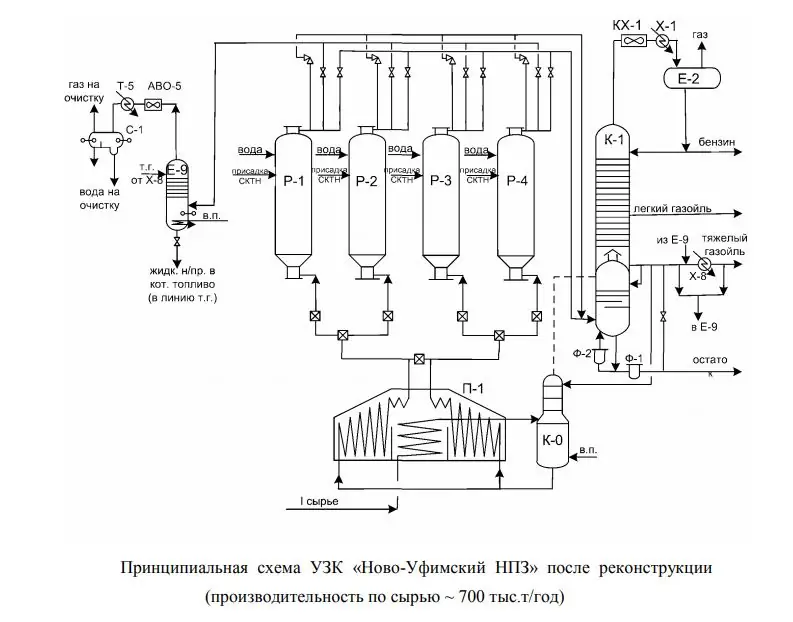
The operation of the first ultrasonic testing unit in Russia was started in 1965 at Ufaneftekhim. The plant's delayed coker is still in operation today. After reconstruction in 2007, its productivity is about 700-750 thousand tons/year in terms of the mass of processed raw materials.
Final products
The following substances are obtained at ultrasonic testing, except for coke:
- coking gases (used as process fuel or processed to obtain propane-butane fraction);
- gasoline;
- coke distillates (fuel, cracking feedstock).
On domestic ultrasonic testing machines, the coke yield is 20-30% by weight. This indicator depends primarily on the quality of raw materials. The metallurgical industry experiences the greatest need for this product (production of anodes and electrodes, aluminum, abrasives, carbides, carbon-graphite materials, ferroalloys). In addition to the first Ufa DCU, other delayed coker units have also been built in Russia: at the Omsk Refinery, Novokuibyshevsk Refinery, LLC LUKOIL-Volgogradneftepererabotka, LUKOIL-Permnefteorgsintez, LUKOIL-Permnefteorgsintez, at the Angarsk Petrochemical Company, NOVOIL OJSC (Ufa), TANECO PJSC (Nizhnekamsk).
Raw materials
Food materials for coking are divided into 2 groups: products of primary and secondary processing. The following substances are used as raw materials in delayed coking units:
- fuel oil;
- half-tar;
- tar;
- coal-tar pitch;
- asph alt and other industrial oil products;
- liquid coal residue;
- heavy pyrolysis and shale tar;
- thermal cracking residues;
- petroleum bitumen and heavy oils.
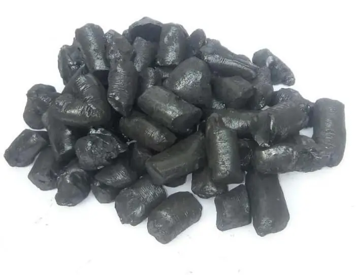
Highly aromatized oil residues are the most common feedstock at present.
Influence on technological parameters
The following parameters of the coking plant depend on the properties of the feed materials:
- efficiency of the reaction chamber;
- quality of products received;
- coke outlet;
- conditions for the process.
The most important raw material parameters are:
- Coking, depending on the content of asph alt-resinous substances. The coking value should be in the range of 10-20%. With a smaller value, the coke yield decreases, and with a larger one, deposits accumulate inside the coils in the furnaces. The coking capacity is determined by the mass of the solid residue in the crucible after heating the oil product sample in it.
- Density.
- Chemical composition. Fromharmful impurities that have the greatest impact on the quality of coke emit sulfur (it should be no more than 1.5% by weight). Depending on the purpose of coke in the technological process, it is preferable to use different types of raw materials. So, to obtain a fibrous structure of the final product, materials with a paraffin base are used.
Coke yield is proportional to feed density and asph altene content.
Coking stages
The technological process in delayed coking units is long and continuous, from the supply of raw materials to the unloading of the finished product. Conventionally, it is divided into 3 stages:
- Decomposition reactions, formation of distillate fractions, intermediates, condensation.
- Significant reduction in the content of unsaturated hydrocarbons in gases, an increase in the molecular weight of the residue components, cyclization reactions.
- Increase in the content of asph altenes in the residue up to 26%, reduction in the amount of resins and oils. Convert liquid residue to solid coke.

Classification
There are 2 main types of delayed coking units according to their layout: single-block and double-block.
Among two-block plants, there are 4 types, which are characterized by the following design and technological features:
- Internal diameter of coking chambers - 4.6 m. Tent heating furnaces, four chambers operating in pairs. The kerosene and gas oil obtained during the coking process are used for heating.
- Cokechambers Ø 5.5 m. Feedstock - straight-run fuel oils with the introduction of highly aromatic hydrocarbons, which increase the yield of a quality product.
- Reactors made of alloyed steel Ø 5.5 m, height 27.6 m, tubular furnaces with a volumetric-laying torch, overhead valves of increased cross-section, radioactive level gauges that allow registering the location of the coke-foam phase separation. The latest innovation helps to better use the useful volume of the reactor. Supply of turbulators with detergent additives to reduce coking of coils, cooled gas oil in helmet tubes.
- Reaction chambers Ø 7 m, height 29.3 m. Axial input of raw material into the reactors, hydraulic system for discharging coke with remote control, electric cranes, warehouses with floor type storage.
Applied equipment
Equipment, which are equipped with installations of this type, are divided into the following groups depending on the purpose:
- Technological, directly involved in the coking process (furnaces, column equipment, heat exchangers, reactor chambers, cubes, refrigerators, pumps, pipelines, instrumentation, taps and other shut-off and switching valves).
- Wastewater - collection and treatment of water for return to the working cycle (cooling and coke extraction operations).
- Equipment for unloading coke from chambers (cubes). In modern mechanized installations, it can be of a mechanical and hydraulic type (slings, winches, combs, cutters, rods, towers, rubber sleeves).
- Devices for transporting and processing the finished product (receiving chutes and ramps, cranes, conveyors, feeders, crushers, warehouses).
- Machines and equipment for mechanization of works.
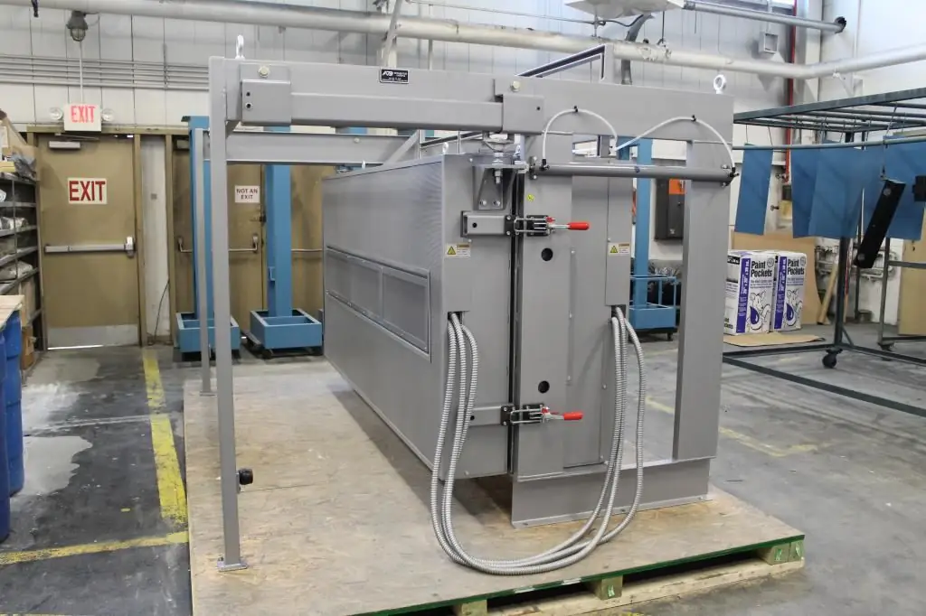
When designing delayed coking plants, it is necessary to carefully consider the design of reaction chambers and furnaces, since the duration of the working cycle depends on the reliability of their operation.
Process parameters
The main parameters of coking technology are:
- Recirculation ratio, defined as the ratio of the total load of the reaction coils of the furnaces to the load of the entire plant in terms of raw materials. With an increase in its value, the yield of high-quality coke, gas and gasoline increases, but the amount of heavy gas oil decreases.
- Pressure in the reaction chamber. Its decrease leads to an increase in the yield of gas oil, a decrease in the yield of coke and gas, and an increase in foaming.
- Technological process temperature. The larger it is, the higher the quality of coke in terms of the amount of volatile substances, its strength and density. The maximum value is limited by the risk of coking of the furnace and pipelines, reducing the durability of the coils. Each type of raw material has its own optimal temperature.
The construction of delayed cokers is associated with high capital costs. Therefore, most often the reconstruction of an already functioning complex of equipment is carried out. This is achieved by reducing the cyclecoking, introducing new reaction chambers or reducing the recirculation ratio.
Operation principle
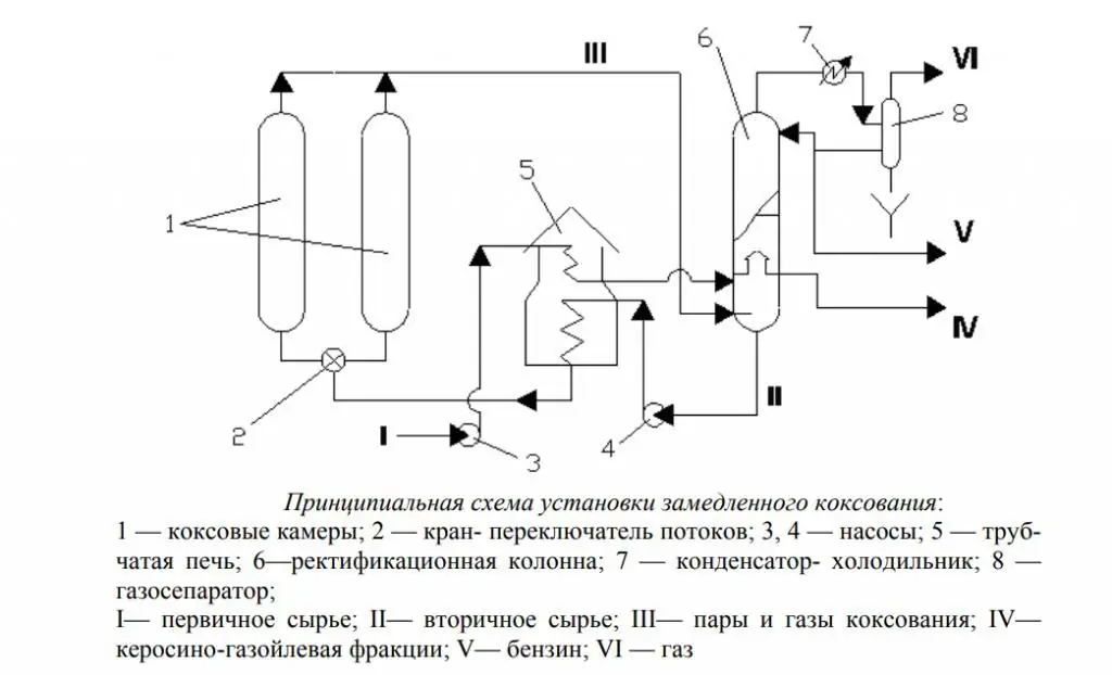
Delayed coking units consist of one or more paired groups of chambers, in which one chamber operates at the stage of coke production, and the other at unloading or in an intermediate state. The process of decomposition of the source material begins in a tube furnace, where it is heated to 470-510 °C. After that, the raw material enters unheated chambers, where it is deeply coked due to the heat that came along with it.
Gaseous and liquid hydrocarbons are discharged for fractional separation in a distillation column. Coke enters the mechanical processing department, where it is unloaded, sorted and transported. A well is drilled in the layer of the finished product, and a hydraulic cutter is placed in it. Its nozzles operate under pressure up to 20 MPa. Pieces of separated coke fall onto a drainage platform where water is drained. The product is then crushed into smaller pieces and separated into fractions. Next, the coke is moved to the warehouse.
The principle diagram of ultrasonic testing is shown in the figure below.
Coke chambers
The chambers are a reactor, which is the basis of the entire installation. The cycle of operation of the chamber is usually 48 hours, however, in recent years, ultrasonic devices operating in 18- and 36-hour modes have been designed.
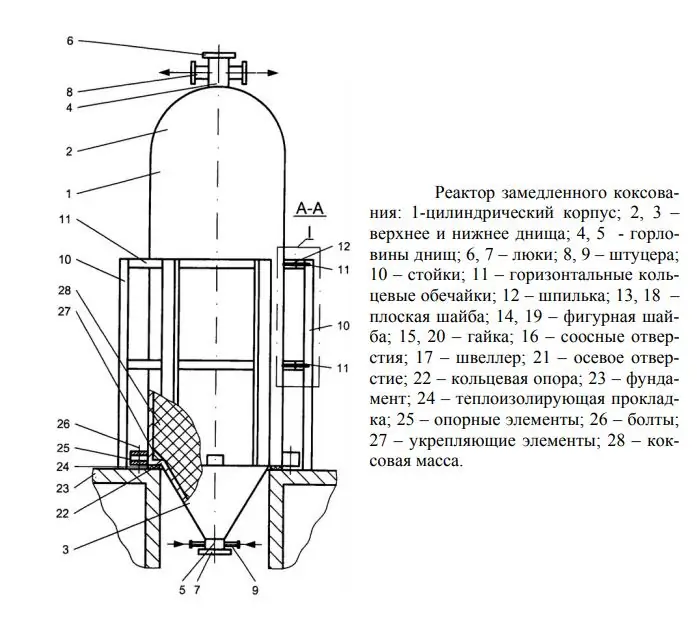
One reactor operation cycle consists of the following operations:
- loading of raw materials, coking process (1 day);
- off (1/2 hour);
- hydrothermal treatment (2.5 hours);
- water cooling of the product, water removal (4 hours);
- unload product (5 hours);
- sealing manholes, pressure testing with hot steam (2 hours);
- heating with oil vapors, switching to working cycle (3 hours).
Design
The delayed coking unit project is being developed in the following order:
- determination of the required productivity, t/year;
- resource base analysis;
- drawing up a theoretical material balance of the coking process for various types of raw materials;
- determination of the main material flows;
- development of the installation concept;
- justification for the size and number of reactors;
- determining the duration of filling one chamber with coke and its hydraulic calculation, drawing up a schedule for the operation of the reactor;
- calculations of the temperature load on the chamber;
- calculation of convection and radiation chambers;
- development of production line layout;
- technological calculations of other main equipment (distillation column, furnaces, refrigerators, etc.);
- development of a monitoring and control system, choice of automation tools;
- description of emergency protection schemes;
- development of environmental aspects and safety measures;
- determination of economic indicators (capital costs, number of service personnel, payroll,production costs for raw materials and auxiliary materials, annual economic effect, product costing).

Calculation of the capacity of the delayed coking unit on an annual basis is made according to the formula:
N=P x t, where P is the capacity of the plant, t/day;
t is the number of working days in a year.
Product output in physical terms according to the base and design options is determined based on the material balance of the installation.
Recommended:
Arc steel furnace: device, operating principle, power, control system
Arc steel-smelting furnaces (EAFs) differ from induction furnaces in that the loaded material is directly subjected to electrical bending, and the current at the terminals passes through the charged material
Diamond boring machine: types, device, operating principle and operating conditions
The combination of a complex cutting direction configuration and solid-state working equipment allows diamond boring equipment to perform extremely delicate and critical metalworking operations. Such units are trusted with the operations of creating shaped surfaces, hole correction, dressing of ends, etc. At the same time, the diamond boring machine is universal in terms of application possibilities in various fields. It is used not only in specialized industries, but also in private workshops
Clothing industry as a branch of light industry. Technologies, equipment and raw materials for the clothing industry
The article is devoted to the clothing industry. The technologies used in this industry, equipment, raw materials, etc. are considered
What is reactive power? Reactive power compensation. Reactive power calculation
In real production conditions, reactive power of an inductive nature prevails. The enterprises install not one electric meter, but two, one of which is active. And for the overexpenditure of energy “chased” in vain through power lines, the relevant authorities are mercilessly fined
Gas piston power plant: the principle of operation. Operation and maintenance of gas piston power plants
Gas piston power plant is used as a main or backup source of energy. The device requires access to any type of combustible gas to operate. Many GPES models can additionally generate heat for heating and cold for ventilation systems, warehouses, industrial facilities

