2026 Author: Howard Calhoun | [email protected]. Last modified: 2025-01-24 13:10:49
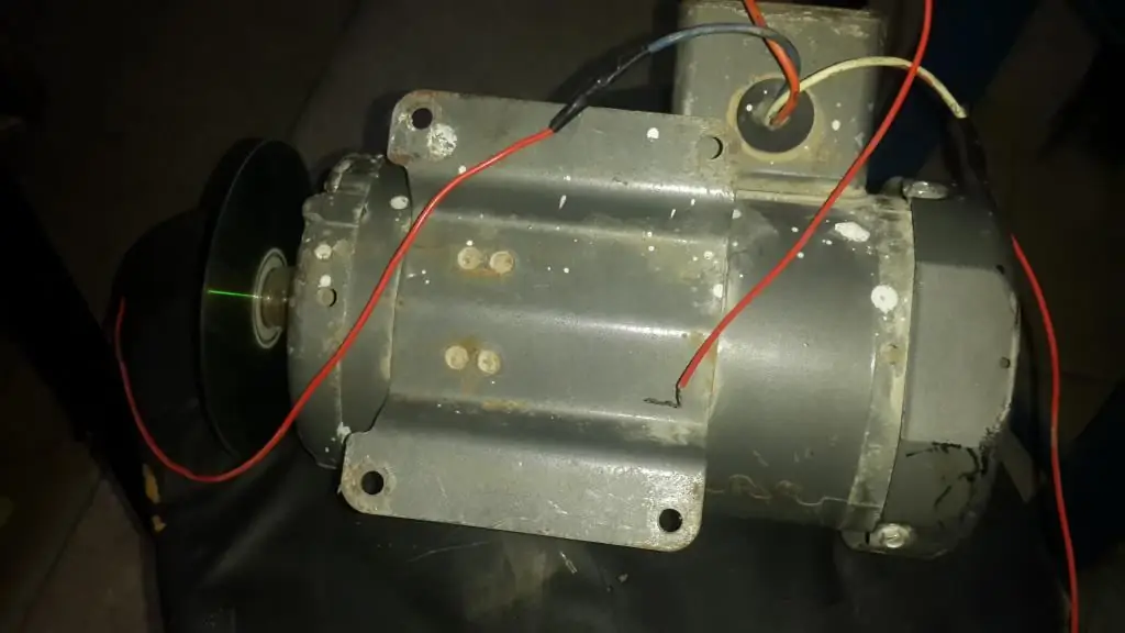
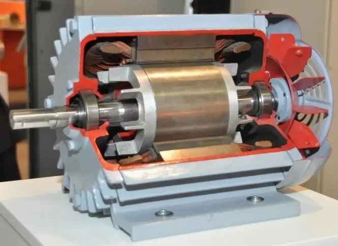
Today, relay-contactor control circuits are most often used. In such systems, the main devices are electromagnetic starters and relays. In addition, a device such as a three-phase asynchronous motor with a squirrel-cage rotor is most often used as a drive for machine tools and other installations.
Description of engines
These types of drives have been actively used due to the fact that they are easy to operate, maintain, repair and install. They have only one serious drawback, which is that the starting current exceeds the rated current by about 5-7 times, and there is also no way to smoothly change the rotor speed using simple control methods.
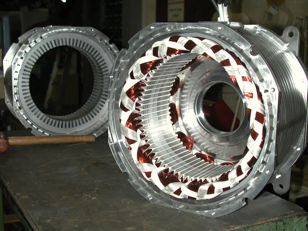
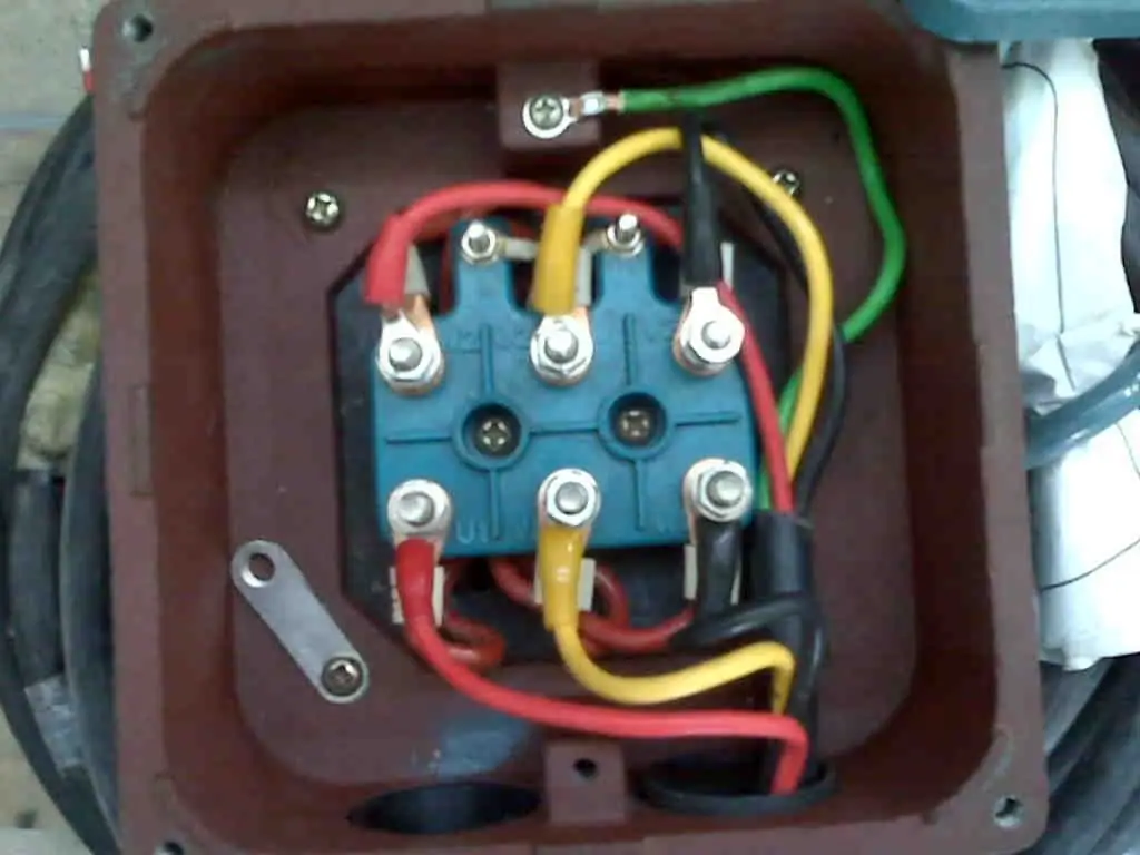
This type of machines began to be actively used due to the fact that devices such as frequency converters began to be actively introduced into electrical installations. Another significant advantage of an asynchronous motor with three-phase current and short-circuitedrotor in that it has a fairly simple scheme for connecting to the network. To turn it on, you only need to apply a three-phase voltage to the stator, and the device will immediately start. In the most simple control schemes, a device such as a packet switch or a three-phase knife switch is used to start it. However, these devices, despite their simplicity and ease of use, are elements of manual control.
This is a huge minus, since in the schemes of most installations it is necessary to use the engine switching circuit in automatic mode. It is also necessary to provide for an automatic change in the direction of rotation of the motor rotor, that is, its reverse and the order in which several motors are put into operation.
Basic wiring diagrams
To provide all the necessary functions that have been described above, it is necessary to use automatic operating modes, and not manual drive controls. However, it is fair to say that some older metal cutting machines still use stack switches to change the number of pole pairs or to reverse.
The use of not only batch switches, but also knife switches in the connection circuits of asynchronous motors (IM) is possible, but they perform only one function - connecting the circuit to the voltage supply. All other operations that the motor control circuit provides are performed under the guidance of an electromagnetic starter.
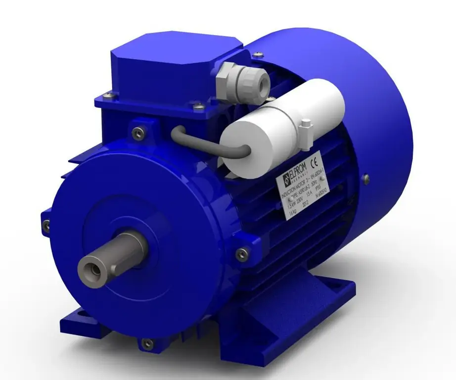
WhenConnecting the HELL circuit with a squirrel-cage rotor through this type of starter provides not only a convenient control mode, but also creates zero protection. Most often, three switching methods are used as motor control circuits in machines, installations and other machines:
- the first scheme is used to control a non-reversible motor, uses only one electromagnetic type starter and two buttons - "Start" and "Stop";
- the second reversing type motor control circuit provides for the use of three buttons and two conventional type starters or one reversing type;
- the third control scheme differs from the previous one only in that two of the three control buttons have paired contacts.
Circuit with electromagnetic type starter
The start of an asynchronous motor in such a connection scheme is carried out by pressing the corresponding button. When it is pressed, a current with a voltage of 220 V is applied to the starter coil. The starter has a moving part, which, when voltage is applied, is attracted to the stationary one, due to which the contacts of the device close. These power contacts supply the input voltage to the motor. Parallel to this process, the blocking contact is also closed. Its inclusion is carried out parallel to the "Start" button. It is because of this feature that when the button is released, the coil is still energized and continues to power the motor to keep it running.
If for any reason during the start of the induction motor, that iswhen you press "Start", the blocking contact would not close or, for example, be absent, then immediately when released, the current would cease to be supplied to the coil, the starter's power contacts would open, and the engine would immediately stop. This mode of operation is called "jumping". It occurs, for example, when operating a beam crane.
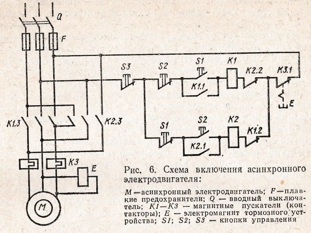
In order to stop a three-phase asynchronous motor with a squirrel-cage rotor, you must press the "Stop" button. The principle of operation in this case is quite simple and is based on the fact that pressing the button creates a break in the circuit, disconnecting the power contacts of the starter, thereby stopping the engine. If the voltage at the power source disappears during operation, the engine will also stop, since such a defect is tantamount to pressing "Stop" and further creating a break in the device circuit.
After the device was stopped by a power outage or power failure, it can only be restarted with a button. This is what is called zero protection in motor control circuits. If instead of a starter a switch or knife switch was installed here, then if the voltage reappears in the source, the engine would automatically start and continue to work. This is considered unsafe for maintenance personnel.
Using two starters in a reversing device
This type of asynchronous motor control circuit, in fact, works in the same way as the previous one. The main difference here isthat it becomes possible, if necessary, to change the direction of rotation of the rotor. To do this, it is necessary to change the operating phases available on the stator winding. For example, if you press the "Start" button KM1, then the order of the working phases will be A-B-C. If you turn on the device from the second button, that is, from KM2, then the order of the operating phases will change to the opposite, that is, C-B-A.
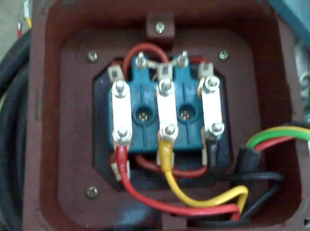
Thus, it turns out that to control an asynchronous motor with a circuit of this type, two "Start" buttons, one "Stop" button and two starters are needed.
When you press the first button, which is usually referred to as SB2 in the diagram, the first contactor will turn on and the rotor will rotate in one direction. If it becomes necessary to change the direction of rotation to the opposite, you must press "Stop", after which the engine is started by pressing the SB3 button and turning on the second contactor. In other words, to use this scheme, an intermediate press on the stop button is necessary.
Because it becomes more difficult to control the operation of the engine with such a scheme, there is a need for additional protection. In this case, we are talking about the operation of normally closed (NC) contacts in the starter. They are necessary in order to provide protection against simultaneous pressing of both "Start" buttons. Pressing them without stopping will cause a short circuit. Additional contacts in this case prevent the simultaneous inclusion of bothstarters. This is due to the fact that when pressed simultaneously, one of them will turn on a second later than the second. During this time, the first contactor will have time to open its contacts.
The disadvantage of controlling an electric motor with such a circuit is that the starters must have a large number of contacts or contact attachments. Any of these two options not only complicates the entire electrical design, but also increases the cost of its assembly.
Third kind of control scheme
The main difference between this scheme of the engine control system and the previous one is that in the circuit of each of the contactors, in addition to the common "Stop" button, there are two more contacts. If we consider the first contactor, then in its circuit there is an additional contact; SB2 is a normally open (make) contact, and SB3 has a normally closed (break) contact. If we consider the connection diagram of the second electromagnetic starter, then its "Start" button will have the same contacts, but located opposite to the first one.
Thus, it was possible to ensure that when you press one of them with the engine running, the circuit already in operation will open, and the other, on the contrary, will close. This type of connection has several advantages. Firstly, this circuit does not need protection against simultaneous switching on, which means that there is no need for additional contacts. Secondly, it becomes possible to reverse without intermediate pressing on"Stop". With this connection, this contactor is used only to completely stop the working HELL.
It is worth noting that the considered engine start control schemes are somewhat simplified. They do not consider the presence of various additional protection devices, signaling elements. In addition, in some cases it is possible to power the electromagnetic coil of the starter from a source of 380 V. In this case, it becomes possible to connect only from two phases, for example A and B.
Control circuit with direct start and timing function
The engine is started as usual - with a button, after which the voltage will be applied to the starter coil, which will connect the AD to the power source. The peculiarity of the circuit is as follows: along with the closing of the contacts at the starter (KM), one of its contacts will close in another circuit (CT). Because of this, the circuit is closed, in which the braking contactor (KM1) is located. But its operation at this moment is not carried out, since the opening contact KM is located in front of it.
To turn off, there is another button that opens the KM circuit. At this time, the device is disconnected from the AC mains. However, at the same time, the contact closes, which was in the braking relay circuit, which was previously referred to as KM1, and the circuit is also turned off in the time relay, which is designated as KT. This is what leads to the fact that the contactor KM1 is included in the work. In this case, theswitching the motor control circuit to direct current. That is, the supply voltage is supplied from a built-in source through a rectifier, as well as a resistor. All this leads to the fact that the unit performs dynamic braking.
However, the work of the scheme does not end there. The circuit has a time relay (CT), which starts counting the braking time immediately after it is disconnected from the power supply. When the allotted time to turn off the engine expires, the CT opens its contact, which is available in the KM1 circuit, it turns off, due to which the supply of direct current to the engine also stops. Only after this does a complete stop occur, and it can be considered that the engine control circuit has returned to its original position.
As for the intensity of braking, it can be adjusted by the strength of the direct current that follows through the resistor. To do this, you need to set the required resistance in this area.
Scheme for the operation of a multi-speed motor
This control scheme can provide the possibility of obtaining two motor speeds. To do this, the sections of the stator half-windings are connected to a double star or to a triangle. In addition, in such a case, the possibility of reversing is also provided. To avoid malfunctions of the engine control system, in such a complex circuit there are two thermal relays, as well as a fuse. On the diagrams, they are usually marked as KK1, KK1 and FA, respectively.
Initially it is possible to start the rotor at low RPM. To do this, the scheme usually providesa button that is labeled SB4. After pressing it, it starts at a low frequency. In this case, the stator of the device is connected according to the usual triangle scheme, and the existing relay closes two contactors and prepares the motor for connecting power from the source. After that, you need to press the button SB1 or SB2 to determine the direction of rotation - "Forward" or "Back", respectively.
When the run-up to low frequencies is completed, it becomes possible to accelerate the engine to high speeds. To do this, the SB5 button is pressed, which disconnects one of the contactors from the circuit and connects the other. If we consider this action from the point of view of the operation of the chain, then a command is given to move from a triangle to a double star. In order to completely stop the work, there is a "Stop" button, which is marked on the diagrams as SB3.
Button post
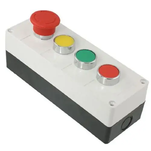
This equipment is intended for switching, that is, connecting circuits in which alternating current flows with a maximum voltage of 660 V and a frequency of 50 or 60 Hz. It is possible to operate such devices in networks with direct current, but then the maximum operating voltage is limited to 440 V. It can even be used as a control panel.
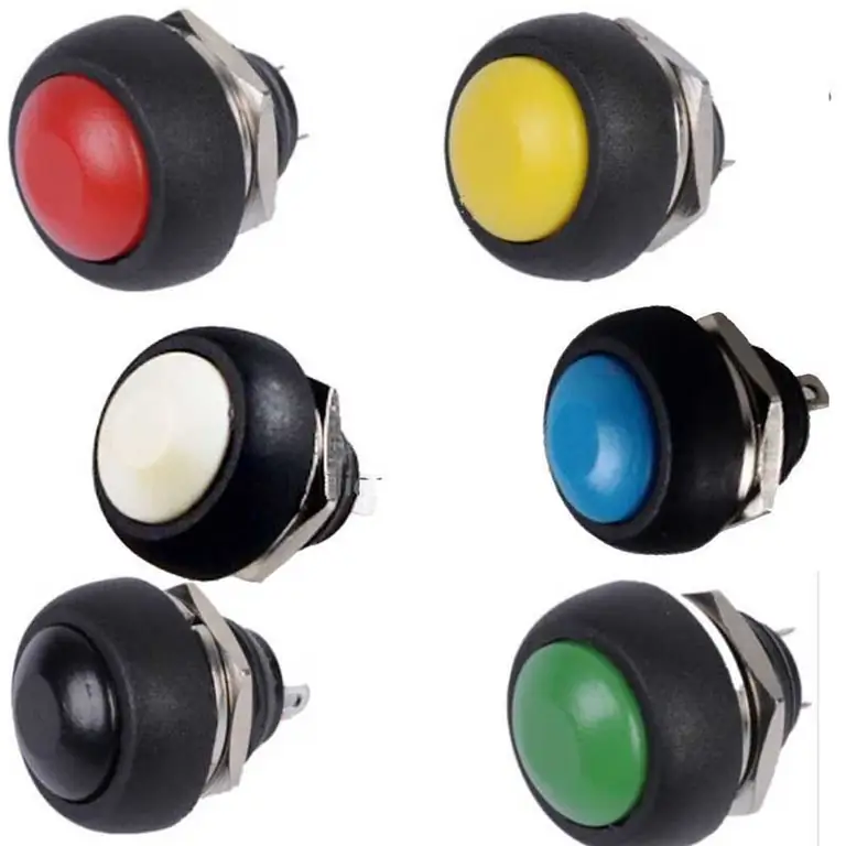
A regular button post has the following design features:
- Each of its buttons is unlatched.
- There is a "Start" button, which most often has not only green color, but also normally-wired type contacts. Some models even have a backlight that turns on when pressed. Purpose - introduction to the work of any mechanism.
- "Stop" is the button that is colored red (most often). It is located on closed contacts, and its main purpose is to disconnect any device from the power source in order to stop its operation.
- The difference between some devices is the material used to make the frame. It can be made from metal or plastic. In this case, the case plays an important role, as it has a certain degree of protection depending on the material.
Key Benefits
Among the main advantages of such devices are the following:
- complete set of this device may not always be standard, it can be adjusted according to the wishes of the customer;
- body is usually made of non-flammable refractory plastic or metal;
- there is good sealing, which is achieved due to the presence of a rubber gasket between the cover and the contacts inside;
- the seal for this button post is under good protection from any aggressive environmental factors;
- there is an additional hole on the side to make it convenient to insert the desired cable;
- all fasteners available at the post are made of high-strength stainless steel.
Post type
There are three types of fasting - PKE, PKT and PKU. The first is usually used to work with machines forwoodworking for industrial or home use. PKU is used in industry, but only at those facilities where there is no danger of explosion, and the concentration of dust and gas does not rise above the level that can disable the device. PKT are exactly those posts that can be used in control circuits for three-phase asynchronous motors with a squirrel-cage rotor, as well as other motors of an electrical type. In addition, they are also widely used to control equipment such as overhead cranes, overhead cranes and other devices designed to lift heavy loads.
Recommended:
Control of cash operations of the bank. Overview of cash transactions control systems

Since various kinds of fraud often occur in the field of cash register accounting, every year the control of cash transactions becomes more and more complicated, tougher and modernized. This article discusses the role of the cash desk in the enterprise, the rules of conduct, as well as methods and systems for monitoring operations
Control object, control subject - complementary concepts

In management there are two concepts such as the object of management, the subject of management. Each organization is represented by an association of two subsystems. One of them is leading, and the other is controlled. But in both cases, they represent relationships between people
The most powerful engine in the world. Engine production
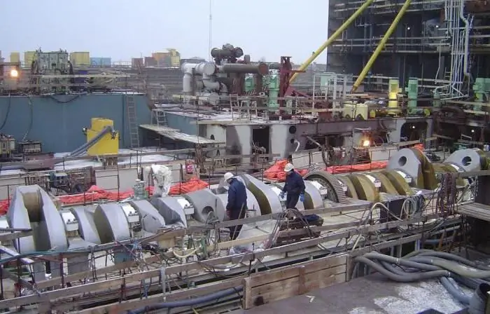
Shipping companies sometimes order such powerful machines as supertankers and container ships. They require ever stronger installations, among which is (and occupies the most important place) the motor. The most powerful engine in the world is currently manufactured in Finland by a company called Wartsila. This is a diesel internal combustion unit, the power of which is up to 100,000 kW
Push-button control posts. Push-button PKU control post
Push-button control posts: description, types, purpose, features. Push-button PKU control post: characteristics, maintenance, photos
How asynchronous machines work and who invented them
Asynchronous electric machines got their name because their angular velocity depends on the magnitude of the mechanical load on the shaft. Moreover, the higher the resistance to torque, the naturally it spins more slowly

