2026 Author: Howard Calhoun | calhoun@techconfronts.com. Last modified: 2025-01-24 13:10:26
As welding technologies improve, the risks of various kinds of defects and deviations from standard parameters are reduced. Nevertheless, even automatic and robotic welding machines do not allow completely eliminating the risks of obtaining poor-quality joints. Therefore, regardless of the applied technology for the production of welding operations, after its execution, a procedure for a comprehensive check of the quality of the welds is implemented. The visual inspection method is the initial step in the overall process of welding inspection.
Basics
The control of welding joints should be understood as a technological procedure that can be performed at different stages of the production process, but in any case it should be carried out in accordance with regulatory guidelines. To the basic principles of this operationinclude:
- Inspection is performed on parts, blanks and finished products in order to determine the compliance of this object with design characteristics.
- When performing control, the current status of the object of study, features of structural and dimensional parameters should be taken into account.
- Only qualified personnel familiar with the technical rules of visual inspection in accordance with GOST R EN 13018-2014 are allowed to check. In addition, the vision of the direct participants in the test must meet the requirements of ISO 9712.
- During the inspection operations, the target object must not be subjected to destruction and mechanical stress, which, in principle, can lead to changes in the structure of the material and its performance.
Principles and objectives of the method
The essence of this control method is to study the surfaces of target objects by external inspection. At the initial level, the operator examines the weld zone using his own vision, but special technical devices can also be used. For example, optical instruments make it possible to study surfaces in terms of approaching and accentuating the zone by means of light radiation. This makes it possible not only to visually control, but also to fix certain parameters of an already identified defect.
As a result of the inspection, a defectological map should be formed indicating the places of damage, flaws and deviations in the place of the welded joint. Based on the data obtained, the seam is finalized or disposed ofdetails depending on site restoration capabilities.
Target defects to detect
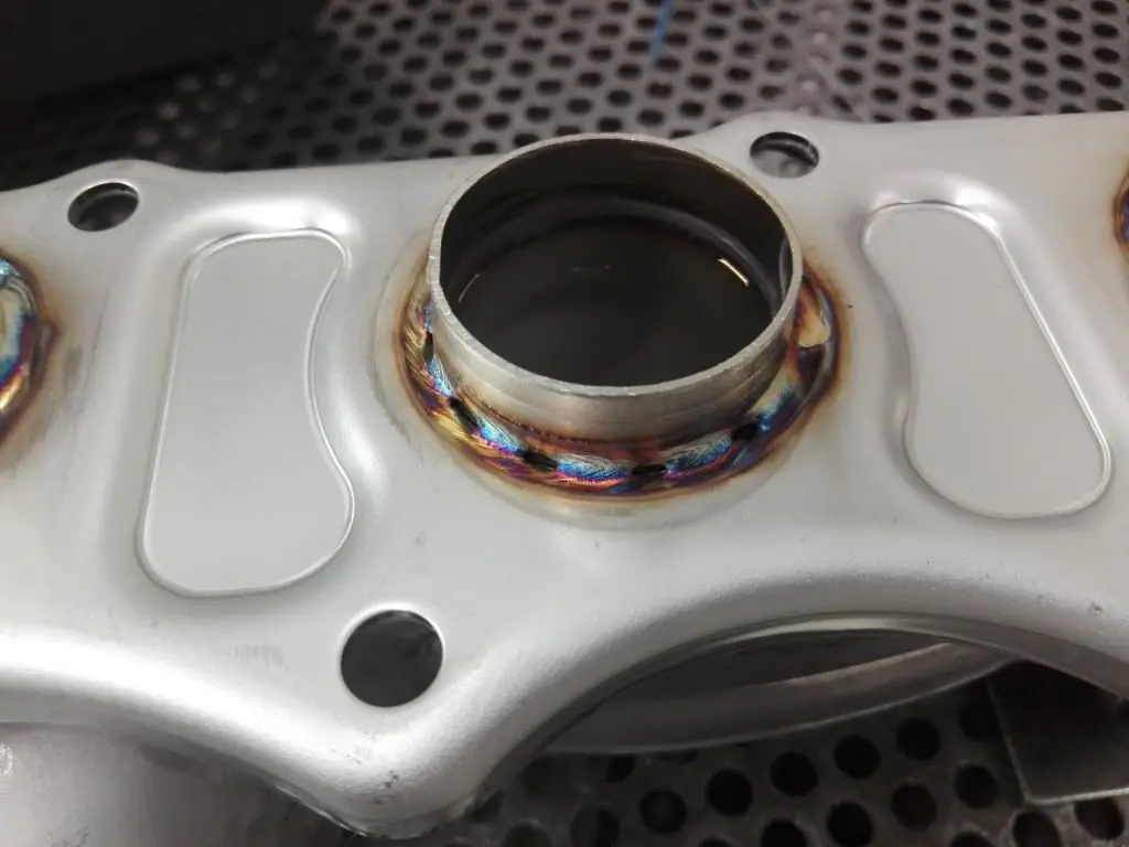
The main defects and deviations of the weld, which are detected during external control, include:
- Lack of penetration. Leakage or partial misalignment of the surfaces of two parts due to insufficiently melted edges.
- Concavities. On the contrary, excessive penetration of the weld root was allowed, as a result of which the structure of the base was deformed. In this case, visual inspection only fixes the fact of the presence of a defect, and its characteristics are revealed by internal non-destructive testing methods.
- Undercuts. An indentation that follows the alloy line. Allowed due to incorrect arc direction during welding or due to external mechanical damage.
- Bumps. Usually formed due to improper supply of a protective gas mixture or in violation of the temperature regime during the melt.
Applied instrument of control
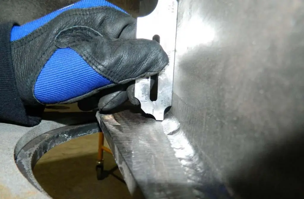
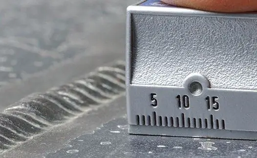
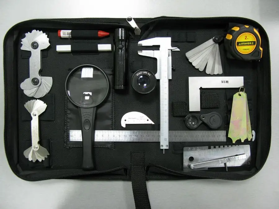
At a basic level, the simplest visual inspection tools are used, including magnifiers, calipers, rulers and squares. Eddy current and ultrasonic thickness gauges, which give an idea of the dimensional parameters of defects, can be attributed to specialized devices for professional testing.
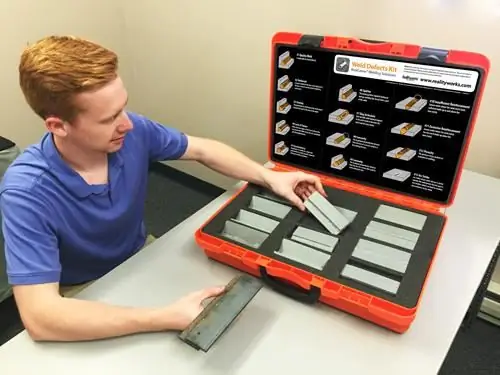
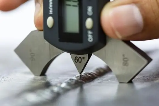
Widely used for visual inspection and templates, by which, even without specific measurements, it is possible to determine the deviations of the characteristics of the seam from the standard values. In this way of comparison, the shapes of gaps, edges andassembled parts for subsequent connection. Especially for determining the degree of waviness and surface roughness, profilers-profilometers are used.
Features of laser visual inspection
Both human vision and the capabilities of optical instruments have their limitations when examining surfaces with increased observation accuracy. The most effective tool for in-depth visual inspection of welded joints is a laser scanning system with a high-precision camera. Such devices make it possible to make three-dimensional graphic images of observation sites with instant calculation of weld errors. That is, in the mode of operational analysis, it makes a map of defects in the form of a computer model.
Moreover, the device does not just provide the necessary list of initial parameters for subsequent analysis, but, depending on the data processing algorithms, it can independently classify the connection based on geometric indicators, type of defect, etc. The scanning module with a microprocessor makes a decision about the possibilities further use of the part, taking into account the severity of the detected deviations from the norm.
Preparing the inspection site
According to the regulations, work is carried out on a stationary site, equipped with special platforms, stands and tables to accommodate the object and equipment under study. Often, control is carried out within the production area, which is due to the minimization of logistics costs when movingparts from the immediate place of welding to the control zone. In this case, special attention is paid to the fences from the area where technological operations are performed. The place for the study is also selected taking into account the sanitary and environmental situation, which is especially true for enterprises in the chemical and metallurgical industries.
The better the work area is illuminated, the more accurate the results of the visual inspection of welds will be. Illumination should be bright enough for a reliable study of the controlled surface, but not exceed 500 Lx in terms of luminous intensity.
Preparing for inspection
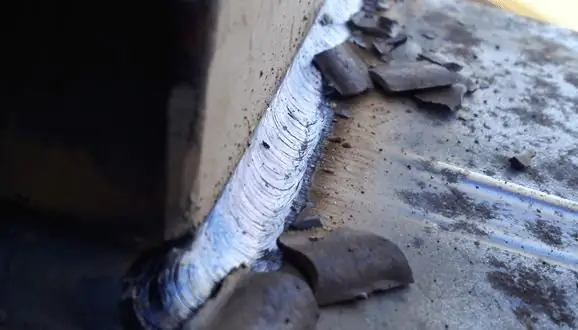
Regardless of the type and characteristics of the object being examined, its surfaces must be properly cleaned. Any foreign coatings that are not part of the natural structure of the seam are subject to removal. This applies to scale, paint, dirt, traces of rust and slag left after welding. Objects whose surfaces have tint colors are not always allowed to be controlled. If the controlled surface is part of the operating equipment, then the unit must be stopped for the duration of the study.
As a rule, this refers to technological equipment that has been repaired by welding. We are talking about ventilation systems, cooling systems, compressor units, etc. During the preparation, special attention is paid to the visual control tool kit and consumables that will be used in the course of work. The tools must beproperly configured, calibrated, tested for performance and accuracy.
Incoming control procedure
The first stage of external control within the production process, which aims to check the blanks and parts before assembly operations. At this stage, cracks, sunsets, nicks, delaminations and shells of welds are detected, which are incompatible with the requirements of further technological operations. According to the instructions for visual inspection at the entrance inspection stage, the length of the sections that can be checked without auxiliary equipment can be no more than 100 mm.
Otherwise, measuring instruments are used, which allow to fix the geometrical parameters of defects in a streaming mode. By the way, in addition to directly welded seams, at this stage the condition of the edges of parts that will still be assembled by welding can be assessed.
Accounting for controlled parameters after welding
The main stage of work on the visual inspection of parts, which is carried out after the completion of the assembly of structures by thermal welding. The main object of research is surfacing in the form of a finished joint. As a rule, layer-by-layer visual inspection of welds is carried out with fixation of surface defects. If it is not possible to accurately identify and evaluate the parameters of fistulas, cracks and signs of destruction of the weld bead, then an internal analysis of the structure is performed with the connection of radiation or ultrasonic equipment.
Measured parameters during control
From the point of view of the requirements for the technological assembly of metal parts and structures, it is more important not to fix the very fact of the presence of a defect, but its dimensional indicators. In accordance with the instructions for visual and measuring control, the following values should be recorded during a comprehensive study:
- Width, length and depth of the seam.
- The size of the bulge of the seam.
- Parameters for chips, cracks and shells.
- Cut depth.
- Cut of fillet weld.
- Length of discontinuities.
On an individual basis, according to the design requirements, a map of the relative position of the seams can also be drawn up. For example, maintaining a certain distance between connection points is often a condition for ensuring the reliability of the entire structure, so taking into account the gaps is considered as one of the paramount control values.
Inspection for corrective actions
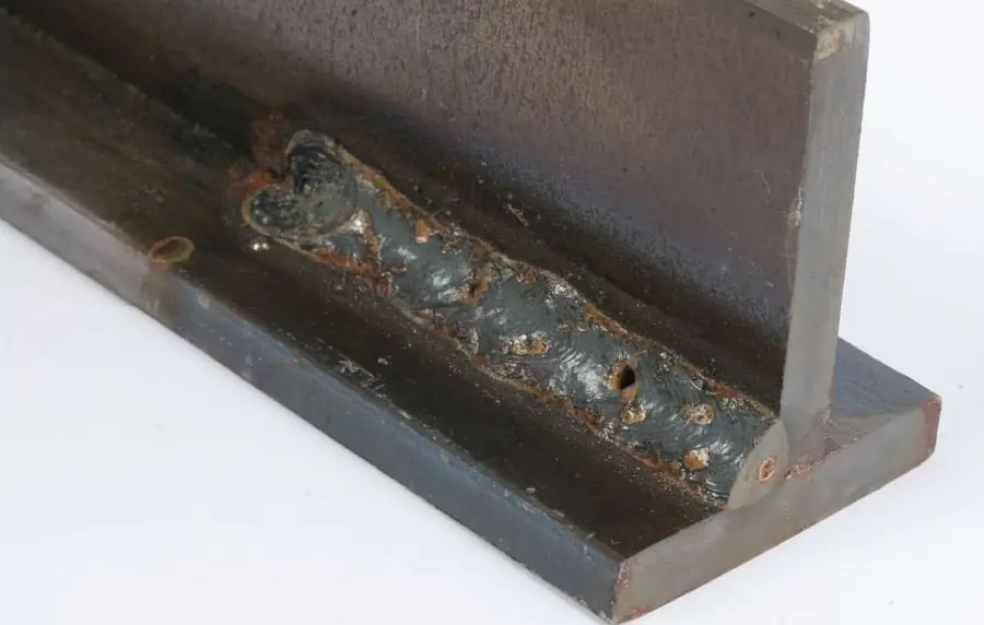
In the process of repairing defective seams and restoring the damaged structure of metal parts, control operations are also performed, the objectives of which include:
- Tracking the completeness of the defect.
- Identification of new defects caused by the use of means for correcting the structure of the seam.
- Checking the overall shape of the defective area.
- Monitoring the cleanliness of the site - in particular, tracking contamination of the junction with oil, corrosion products, industrial dust, etc.
Alsothe visual method of control allows keeping within the normative limits the parameters of mechanical operations required to correct the structure of the welded joint. In particular, the depth of sampling of a defective seam, the width of the stripping zone, the amount of cutting edges, bevel angles, etc. are controlled.
Register results
Control data are recorded in a special register, after which documentation is drawn up in the form of an act, protocol or conclusion based on the results of the survey. When visual quality control is performed, a mark is also placed on the surface of the target area indicating the results of the inspection. For example, it can be a stamp with access to further technological operations within the production process. Otherwise, the blank is sent for repair or revision.
Conclusion
Technologies for organizing and carrying out control and verification operations in relation to solid parts and materials are constantly being improved, making it possible to detect its smallest defects without damage to the object of study. Nevertheless, the simplest methods of visual inspection are still actively used, which are significantly limited in the possibilities of point control.
This practice is really incomparable in terms of efficiency with modern means of non-destructive internal analysis of the same welds. But, as noted in the instructions for visual and measuring control, external examination affects only the most pronounced defects.surfaces, some of which can be eliminated without the use of specialized devices and consumables. In other words, with minimal costs for the organization of control and technical measures, the most rough marriage is revealed. Further, the workpiece is sent to the next stages of more precise control, which requires the use of specialized magnetic, X-ray and ultrasonic devices, which are not advisable to use in the primary control of obvious surface defects.
Recommended:
Inventory: what is it, features of the conduct, necessary forms and acts

Accountants know that inventory is an indispensable and necessary measure for keeping records. No less information about it is possessed by those who are responsible for managing divisions, departments, and the company as a whole. Individual specialists from different departments can take part in the inventory. At some enterprises, this is the responsibility of a special department of material support
What is radiographic testing? Radiographic control of welds. Radiographic control: GOST
Physical bases of radiation control methods. Features of radiographic control. The main stages of radiographic control of welds. Safety precautions in the production of radiographic control. Normative and technical documentation
Debt novation: the essence of the procedure, the procedure for carrying out, the necessary documents

Debt novation is a universal and popular legal procedure that allows you to update a deal and make it profitable for both parties. Its implementation is regulated by the legislation of the Russian Federation. The nuances of drawing up and concluding an agreement, the conditions under which it is considered legitimate are given in the article
Belarusian currency stock exchange. Markets and auctions, organization and conduct of auctions

Private organization "Belarusian Currency Stock Exchange" began its work on December 29, 1998. This is an open joint stock company, whose shareholders are 124 private individuals
Certification of welding technology: types, procedure for preparation and conduct

Currently, welding is one of those types of work that is considered the most common. However, not everyone knows that in order to provide such services, it is necessary to pass the certification of welding technology

