2026 Author: Howard Calhoun | calhoun@techconfronts.com. Last modified: 2025-01-24 13:10:27
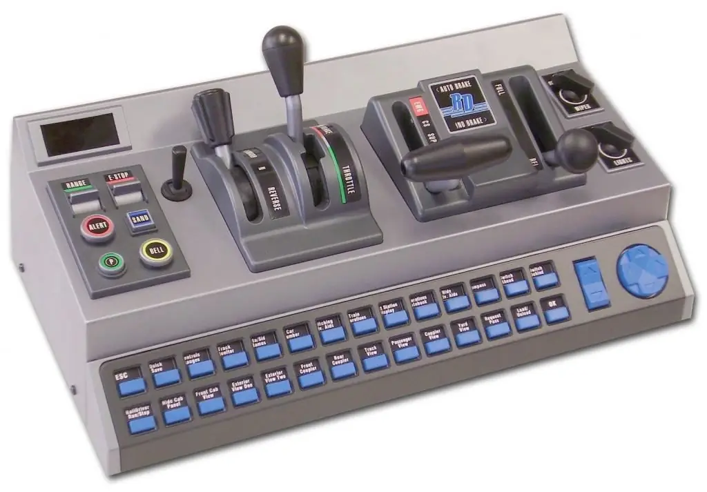
The use of a variety of vehicles today is very active. They all have in common that they need to be managed. The driver's controller is also designed for control. With it, you can remotely control the traction motor in braking or traction mode.
General description of the purpose of the element
With the help of the control controller, it is possible to connect to a low voltage source, as well as turn off the control circuit in the desired sequence of wires. In other words, with the help of this device, it is possible to turn on and off high-voltage devices in the desired sequence during start-up, stop, while regulating the speed of movement and changing the direction of movement when driving an electric locomotive. The driver's controller is equipped with a small number of handles. Each of them has several main positions, each of which will correspond to a certain mode of operation of the power circuit. By switching these handles, the driver is able to control the vehicle.
Design of the device
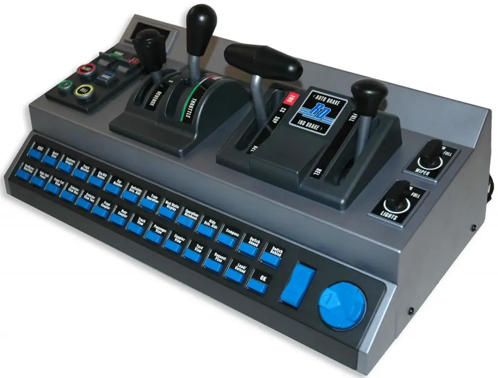
There are a few requirements to keep in mind when designing a driver's controller. First, it must be designed in such a way as to ensure maximum simplicity and ease of use. Secondly, the simplest possible kinematic component for the locking mechanisms should be provided. Thirdly, the dimensions and weight of the entire mechanism should be minimized as much as possible. Among other important design requirements, it is worth highlighting the need to ensure high reliability of all its switching mechanisms, convenience during inspection and during repair of the driver's controller.
In addition, all handles must be placed on the console so as to ensure not only simplicity and convenience of their use, but also in such a way that while driving the locomotive, the driver is not distracted from observing the signals, tracks, network. The driver's controller has interlocking interlocking mechanisms. This eliminates the erroneous movement of two handles opposite in function by the driver.
Zero position
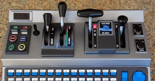
Another important point in the operation of any driver's controller is the zero position of one of the handles. Most often it becomes reverse or reverse-selective. Its main feature is the possibility of removal. It can be removed from the control panel only after moving to the zero position. The peculiarity is that such a lever can be moved to a similar positiononly after all other handles have been moved to the zero position. It should be noted here that the design of the driver's controller assumes the presence of only 1 removable reversing or reversing-selective handle for all control panels, despite the fact that the controller itself will be installed in each control cabin of the locomotive.
This whole system is necessary to ensure that the driver cannot mistakenly leave any handle on one of the controllers. This would cause malfunctions in the normal operation of the electrical circuit when the electric locomotive or electric train is controlled from another controller.
Basic types
The purpose of the driver's controller remains unchanged for any design. To date, there are two main types - drum, cam.
As for the design of drum controllers, in this case, the closing and opening of the wires of the control circuit will be carried out using special segments located on the drum. The so-called fingers are attached to this segment, which, in turn, are connected to the corresponding wires for controlling the electrical circuit. The fingers themselves are attached to the rack.
If we talk about cam controllers, then in this case, instead of a drum, cam contactors or contactor elements are used to close the control wires of the circuit. These elements are mounted on a special rack, and cam washers act on them.
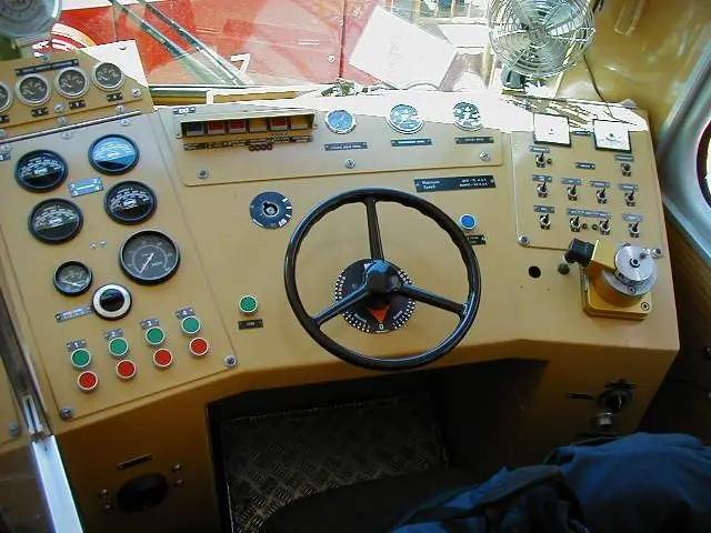
Description of KME-8 controller
In order to better understand the purpose and operation of the controller, we can take a few specific examples. Many electric freight locomotives have a device such as KME-8.
As for its design, it refers to cam devices. If we talk about the KME-8 controller, then it consists of the following main parts: a body with a cast base, a cast cover and several vertical racks. The front of the entire body is covered with a casing, there is also a casing at the back, but already removable. The same contactor elements for control are attached to the rear vertical racks of the controller. Moving contacts will be controlled by cam washers, which are put on special vertical shafts. It is the rotation of these shafts that the driver will control by moving the controller handles.
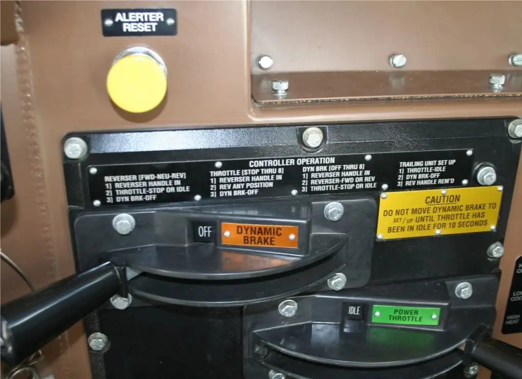
Handle design
You should start with the main lever, which, of course, is connected to the main shaft. This lever allows you to control the traction motors in the appropriate mode and at the same time has 37 positions, not counting zero.
Next, you should pay attention to the brake handle, which is connected to the brake shaft. If you move the lever clockwise, then the positions of the driver controller in this case are limited to 15, not counting zero. Moving the handle will mean regulating the excitation current in regenerative mode. This lever can also be rotated counterclockwise. In this case, he will have only 4 positions, which will weakenexcitation of traction motors.
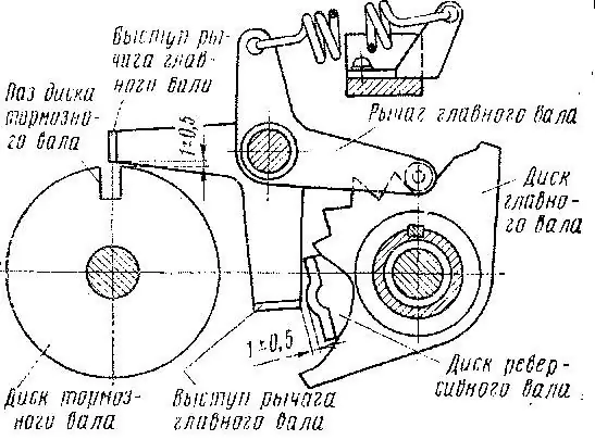
To fix both the main and the brake handle in one place, a latch or a special ledge can be used. If we talk about the latch, then it has a tooth that moves into a special slot due to the action of the spring. In order to move the lever from its place, that is, move it to another position, you will need to press the latch against it so that the tooth comes out of the groove. After that, the handle can be moved, the latch is released, and the lever can be moved until it hits the next groove.
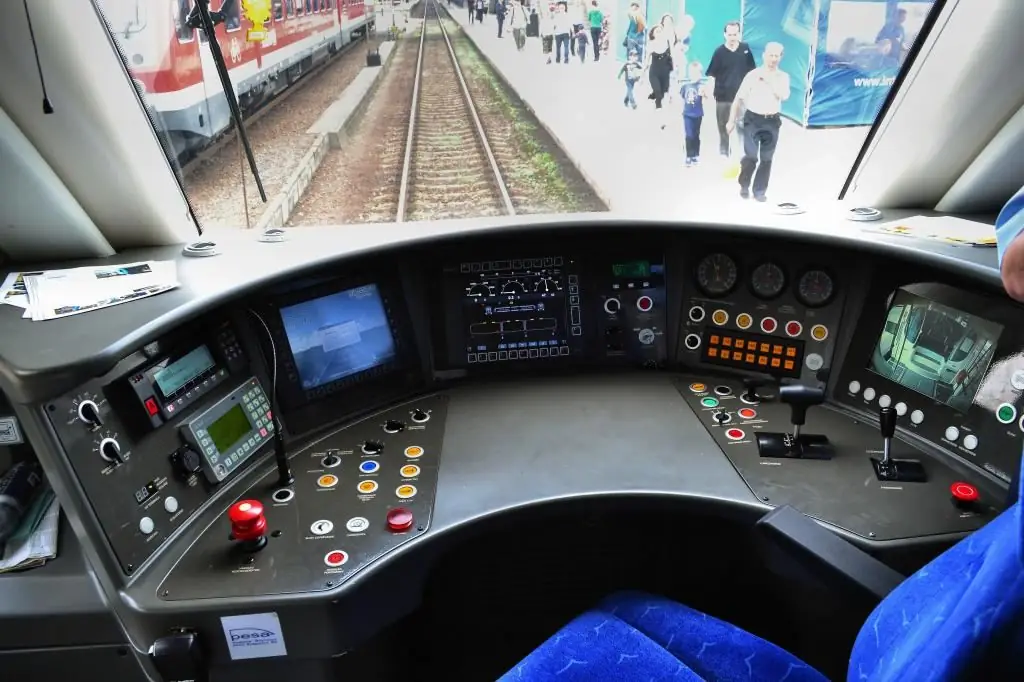
Assigning a reverse or reverse selective stick
As for the most important handle - reversible-selective, it is connected to the same shaft. Using ball bearings, it is mounted on top of the brake shaft. The design feature is as follows. The reversing selective shaft mounted on the brake shaft is connected to the second reversing selective shaft by means of a gear. The second shaft is mounted on the main one. As for the lever positions of this type, it has nine positions. One of them is zero, and 4 positions in each direction.
When moving "Forward" counterclockwise - 4 positions, when moving "Back" clockwise - 4 more. When moving the lever forward, to the first position, the "M" position will be turned on, corresponding to work in traction mode. The next three positions will correspond to different connection schemes for traction motors in the braking mode. This will be a parallel connection."P", series-parallel "SP" and serial "C". As for the positions when moving the handle back, they will all be the same.
Locomotive controller
The locomotive driver controller is designed for ion control of the diesel locomotive power plant. If in the case of an electric locomotive, switching the reversing handle changes the control circuits, then for a diesel locomotive, moving such a lever will mean a change in direction of movement.
As for the design, the controller is assembled from a welded body, a steel cover, two drums - main and reverse. In addition, there is a reversible handle and steering wheel. There are also cam washers on the shafts of this controller. With these washers, you can close and open the contact elements in the desired sequence.
Recommended:
Classification of engines. Types of engines, their purpose, device and principle of operation
Nowadays, most vehicles are powered by an engine. The classification of this device is huge and includes a large number of different types of engines
Reservoir breathing valve: purpose, device, principle of operation, verification
Oil refineries and technological complexes using oil and gas products contain a system of pipelines for servicing fuel materials in their working infrastructure. Maintaining sufficient performance in the circulation circuits of the same oil requires the use of special plumbing fittings. Its key element is the reservoir breather valve, through which the pressure is regulated
General purpose engines: device, principle of operation, application, photo
Automotive equipment is mainly equipped with standardized internal combustion engines (ICEs), the design of which is focused on placement in the engine compartment. However, there is a great demand for power units of this kind in the garden equipment segments, from manufacturers of snowplows, snowmobiles, etc. Moreover, the requirements for integration and operational parameters in such cases differ sharply from automotive standards
Magnetohydrodynamic generator: device, principle of operation and purpose
Not all alternative energy sources on planet Earth have been studied and successfully applied so far. Nevertheless, humanity is actively developing in this direction and finding new options. One of them was obtaining energy from an electrolyte, which is in a magnetic field. Typical operation cycle and main classifications of MHD generators. List of main characteristics. Perspective and applications
Coke oven batteries: device, principle of operation, purpose. Coke production technology
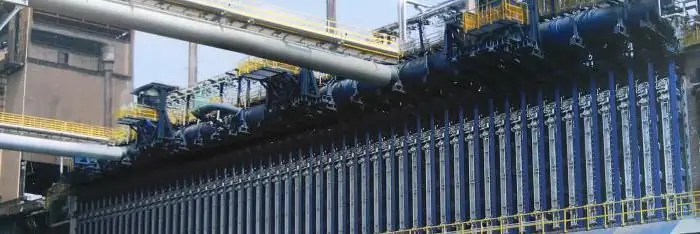
Coke oven batteries are a complex and important industrial facility. We will talk about its work and device in the article

