2026 Author: Howard Calhoun | [email protected]. Last modified: 2025-06-01 07:12:56
In the process of welding, various connections are obtained. Welding seams are able to connect not only metals, but also other dissimilar materials. The elements docked into an integral knot represent a connection that can be delimited into several sections.
Weld zones
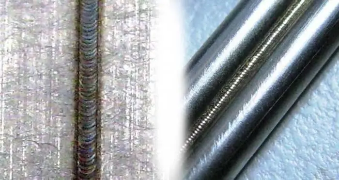
The joint obtained during the welding process is divided into the following zones:
- The place of fusion is the boundary between the base metal and the metal of the resulting weld. In this zone there are grains that differ in their structure from the state of the base metal. This is due to partial melting during the welding process.
- Heat-affected area is a zone of the base metal that has not undergone melting, although its structure has been changed during the heating of the metal.
- Welding seam - a section that was formed during crystallization in the process of cooling the metal.
Types of welding joints
Depending on the location of the joined products relative to each other, the connections are divided into the following types:
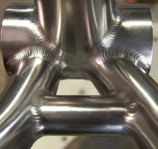
- Butt. Docking of structural elements is carried out in the same plane with ends to each other. Depending on the different thicknesses of the parts to be joined, the ends may shift vertically relative to each other.
- Corner connection. In this case, the ends are aligned at an angle. The welding process is carried out on the adjacent edges of the parts.
- Overlap connection. Parts to be welded are parallel with partial overlap.
- End connection. The elements to be welded are aligned parallel to each other and joined at the ends.
- T-connection. In this case, the end of one part adjoins the side of the other at an angle.
Welding joints also characterize the types of welds, which can be qualified according to some criteria.
Weld measurements
There are several parameters by which all welds obtained can be characterized:
- width is the size between the seam boundaries, which are drawn by visible fusion lines;
- the root of the seam is its reverse side, which is located at the maximum distance from the front part;
- convexity - is determined in the most convex part of the seam and is indicated by the distance from the plane of the base metal to the border of the largest protrusion;
- concavity - this indicator is relevant if it occurs in a weld, because, in fact, it is a defect; this parameter is determined in the place where the seam has the greatest deflection - from it to the planethe base metal is measured by the size of the concavity;
- the leg of the seam - it takes place only in the corner and tee joints; this indicator is measured by the smallest distance from the side surface of one welded part to the boundary line of the seam on the surface of the second.
Types of seams according to the method of execution
- Single-sided welding seams. They are performed with full penetration of the metal along the entire length.
- Double-sided execution. According to the technology, after one-sided welding, the root of the seam is removed, and only after that welding is performed on the other side.
- Single layer seams. Performed by single-pass welding with one deposited bead.
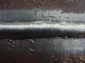
- Multilayer seams. Their use is advisable with a large thickness of the metal, that is, when it is not possible to perform welding in one pass according to the technology. The seam layer will consist of several rollers (passages). This will limit the spread of the heat-affected area and obtain a strong and high-quality weld.
Types of welds by spatial position and length
The following welding positions are distinguished:
- lower, when the welded seam is in the lower horizontal plane, i.e. at an angle of 0º relative to the ground;
- horizontal, the welding direction is horizontal, and the part can be at an angle from 0º to 60º;
- vertical, in this position the surface to be weldedis in the plane from 60º to 120º, and welding is carried out in the vertical direction;
- ceiling, when work is carried out at an angle of 120-180º, that is, the welds are located above the master;
- "into the boat", this provision applies only to corner or tee joints, the part is set at an angle, and welding is carried out "into the corner".
Disaggregation by length:
- continuous, this is how almost all seams are made, but there are exceptions;
- intermittent seams, they only occur in corner joints; double-sided seams of this type can be performed both in a checkerboard pattern and in a chain pattern.
Edging
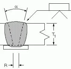
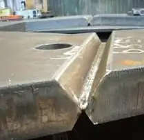
This design feature is used when the thickness of the metal used for welding is larger than 7mm. Grooving is the removal of metal from edges in a specific shape. This process is performed with single-pass butt welding. This is necessary in order to obtain the correct weld. As for thick material, the groove is necessary in order to melt through the initial root pass and then with the next weld beads, evenly filling the cavity, weld the metal through the entire thickness.
Edging can be done if the thickness of the metal is not less than 3 mm. Because a lower value will lead to burns. Cutting is characterized by the following design parameters: clearance - R; edge cutting angle - α; dullness - p. The location of these parameters shows the drawing of the weldingseam.
Beveling increases the amount of consumables. Therefore, this value is tried in every possible way to minimize. It is divided into several types according to the design:
- V-shaped;
- X-shaped;
- Y-shaped;
- U-shaped;
- slit.
Features of cutting edges
For small thicknesses of welded material from 3 to 25 mm, one-sided V-groove is usually used. The bevel can be performed on both ends or on one of them. It is advisable to weld metal with a thickness of 12-60 mm with a double-sided X-shaped groove. The angle α when cutting in X, V shape is 60º, if the bevel is performed on only one edge, then the value of α will be 50º. For a thickness of 20-60 mm, the most economical will be the consumption of weld metal with a U-shaped groove. The bevel can also be made on one or both ends. The blunting will be 1-2 mm, and the gap value will be 2 mm. For a large thickness of metal (over 60 mm), the most effective way is slot cutting. For a welded joint, this procedure is very important, it affects several factors of the seam:
- connection he alth;
- strength and quality of the weld;
- economy.
Standards and GOSTs
- Manual arc welding. Welding seams and joints according to GOST 5264-80 include types, design dimensions for welding, covered with electrodes in all spatial positions. This does not include pipelines.steel.
- Welding of steel pipelines. GOST 16037-80 - defines the main types, cutting edges, design dimensions for mechanized welding.
- Welding of pipelines made of copper and copper-nickel alloys. GOST 16038-80.
- Arc welding of aluminium. Seams are welded. GOST 14806-80 - shape, dimensions, edge preparation for manual and mechanized welding of aluminum and its alloys, the process is carried out in a protective environment.
- Submerged. GOST 8713-79 - welding seams and joints are performed by automatic or mechanized welding on weight, on a flux pad. Applies to metal thickness from 1.5mm to 160mm.
- Welding aluminum in inert gases. GOST 27580-88 - standard for manual, semi-automatic and automatic welding. It is performed by a non-consumable electrode in inert gases with filler material and extends to aluminum thickness from 0.8 to 60 mm.
Weld mark
According to regulatory documents, the presence of welds is shown on assembly drawings or on a general view. Welds are shown as solid lines if they are visible. And if vice versa - then dashed segments. Leaders with one-way arrows are drawn from these lines. The symbol for welding seams is carried out on the shelf from the leader. The inscription is made above the shelf if the seam is on the front side. Otherwise, the designation will be under the shelf. This includes seam information in the following order:
Auxiliary signs. At the intersection of the leader with the shelf can bebadge:
○ - closed seam;
┐ - the seam is welded during installation.
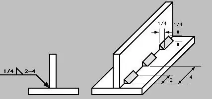
- Designation of welds, their structural elements and GOST connections.
- The name of the seam according to the standard.
- Welding method according to regulatory standards.
- The leg is indicated, this item applies only to corner joints.
- Seam discontinuity, if any. Here the step and location of the welding segments are indicated.
- Additional auxiliary value icons. Let's consider them as a separate item.
Auxiliary symbols
These marks are also applied on top of the shelf if the weld in the drawing is visible, and below it when invisible:
- removal of reinforcement seam;
- surface treatment that will provide a smooth transition to the base metal, eliminating sags and bumps;
- the seam is made along an open line; this symbol applies only to welds visible in the drawing;
- cleanliness of the surface of the welded joint.
To simplify, if all the seams of the structure are made according to the same GOST, have the same grooves and structural dimensions, the designation and standard for welding are indicated in the technical requirements. The design may not be all, but a large number of identical seams. Then they are divided into groups and assigned to them serial numbers in each group separately. On one seam indicate the full designation. The rest are numbered only. The number of groups and the number of stitches in eachof which must be specified in the regulatory documentation.
Recommended:
The main consumable for welding - welding wire
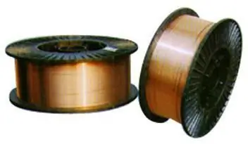
Welding wire is used in various welding operations, it is the main consumable material that acts as an electrode. Welding operations require extensive professional knowledge, a responsible approach to the choice of raw materials. For welding structures, it is unacceptable to use random wire of incomprehensible marking and unknown composition
Welding of ultrasonic plastics, plastics, metals, polymeric materials, aluminum profiles. Ultrasonic welding: technology, harmful factors
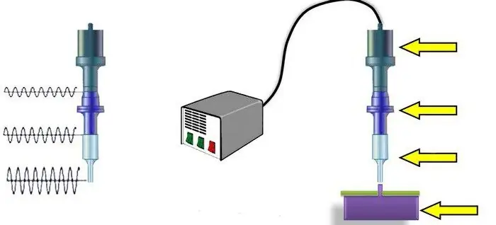
Ultrasonic welding of metals is a process during which a permanent joint is obtained in the solid phase. The formation of juvenile areas (in which bonds are formed) and the contact between them occur under the influence of a special tool
Welded butt joints: features, types and technology
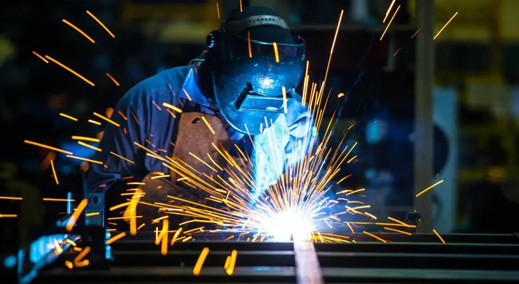
Features and types of welding. Classification of welded butt joints according to various parameters of the weld. Technology for creating a butt joint, depending on the equipment used. Safety measures when performing welding work
Thermite welding: technology. The practice of thermite welding in everyday life and in the electrical industry
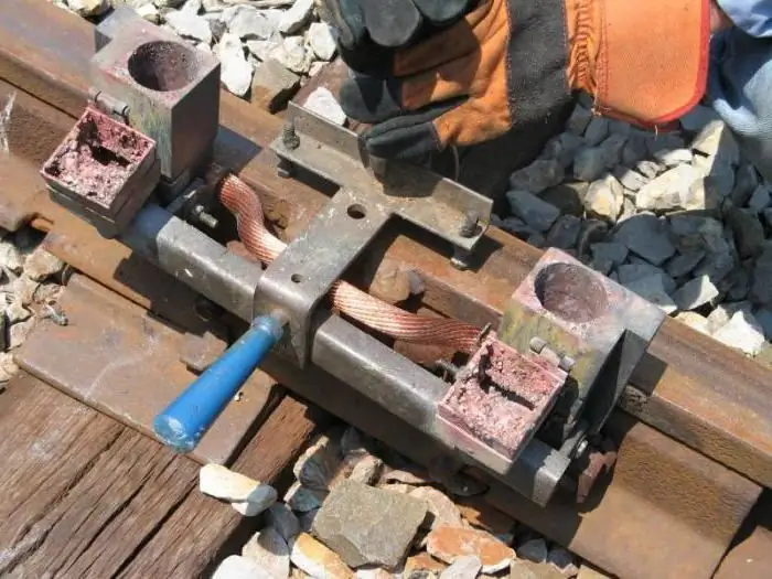
The article is devoted to thermite welding technology. The features of this method, the equipment used, the nuances of use, etc. are considered
Flux for welding: purpose, types of welding, flux composition, rules of use, GOST requirements, pros and cons of application
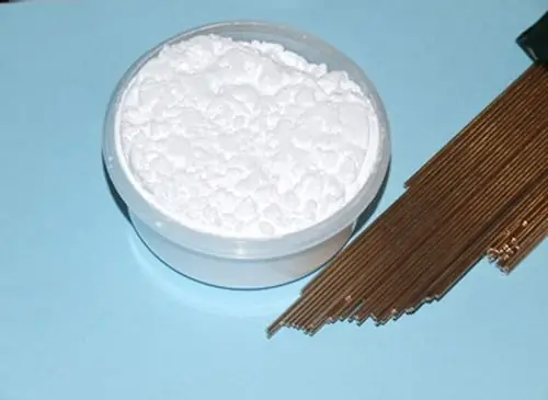
The quality of the weld is determined not only by the ability of the master to organize the arc correctly, but also by the special protection of the working area from external influences. The main enemy on the way to creating a strong and durable metal connection is the natural air environment. The weld is isolated from oxygen by a flux for welding, but this is not only its task

