2026 Author: Howard Calhoun | [email protected]. Last modified: 2025-01-24 13:10:37
Alignment of the shafts of electric motors and mechanisms is carried out in order to ensure that their axes are on the same straight line. Misaligned rotating shafts create significant loads leading to fracture, premature failure of parts and significant noise.

It is not always possible to align the mechanisms coaxially, therefore, couplings are used with compensation for misalignment of the axes by elastic elements. They perform their functions up to a certain amount of misalignment. The alignment of the shafts on the coupling halves is the most convenient. Their surfaces are basic, and measuring devices are attached to them. In the thermal power industry, most of the machines work with elastic pin-sleeve couplings (MUVP). In powerful units, gear couplings (MZ) are used.
Centering options
Shaft alignment with indicators is checked by the following parameters:
- R - mutual radial displacement of the cylindrical surfaces of the coupling halves (radial centering).
- T - end opening differencecoupling halves in vertical and horizontal planes (end or angular misalignment).

Coupling requirements
The allowable misalignment decreases with increasing speed. It is 0.12 mm at 1500 rpm and 0.05 mm at 3000 rpm for MWRP.
Important! When choosing a coupling, it is necessary to check the compliance of its characteristics with the specifications, according to which its axial and radial runout should not exceed 0.05 - 0.08 mm. The fit on the shaft is tight. Prior to disassembly, marks are applied to the coupling halves, by which it will be possible to restore their relative position. Violation of these rules may reduce the centering accuracy.
Horizontal shaft installation
Actually, the axle is not straight as it bends under its own weight and other loads. When centering the unit, it is necessary to control the position of the shafts relative to the horizon. The control is carried out on the bearing journals. You can use the nearby flat surface of the shaft using the level "Geological exploration" (dividing 0.1 mm per 1 m).
Alignment Control Devices
Experienced craftsmen are able to control the alignment by applying a metal ruler to the coupling and determining the alignment by clearance. But for greater confidence, in order to meet the norm, you can use a plate probe or indicator ICH-0, 01. The latter provides the necessary accuracy of 0.01 mm, which is enough to meet the norm.
First, the coupling halves are disconnected, and then on them oron the shafts nearby, devices are installed for centering the shafts of electrical machines. They must be rigid enough so that they do not bend during measurements. Measurements can also be taken with couplings connected.

After installing and strengthening the fixtures, the performance of the indicator mechanism is checked. To do this, pull back and return the measuring rods. In this case, the arrow should return to its original position.
Axial and radial clearances are checked by simultaneously turning both rotors from the starting position through 90°, 180° and 270° in the direction of rotation of the drive.
How to center aggregates?
Before measurements, the tightening of anchors and bearing housings is checked. Loose fastening, cracks in the frame, foundation defects, uneven floor settlement are the causes of misalignment during the operation of mechanisms.
Attachments are installed on the coupling halves, then the misalignment is measured:
- radial in the vertical plane;
- radial in the horizontal plane;
- end in vertical plane;
- end in the horizontal plane.
According to the results of measurements, the position of the axes of the shafts is corrected. To do this, the supports are moved vertically with the help of spacers, and horizontally with bolts located on the frame. The centering bracket is set to the position of the larger value of the misalignment parameter, after which the supports are moved by the amount of the actual misalignment.
Shaft alignment is performed alternately in the horizontal and vertical planes. After the end of the process of moving and fixing the supports, the measurements are made again. If necessary, they are corrected again.
Alignment of pumping units
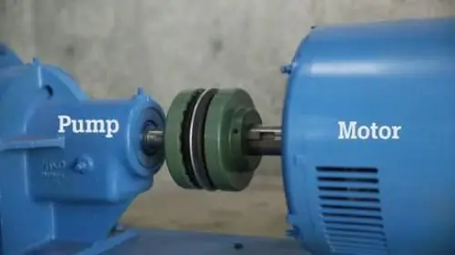
Alignment of pump and motor shafts is necessary to balance rotating parts. This applies not only to the wheel and shaft, but also to the rotor of the electric motor. It is the responsibility of the manufacturer to demonstrate the unit in the operating mode of supply without exceeding the permissible vibration level. Prices for industrial units are high, and with further operation it will be almost impossible to prove the manufacturer's guilt.

Standards stipulate that after start-up, vibration is the responsibility of the customer. Pump tests should be carried out at the regular place of its operation. Particular attention is paid to the foundation and the base frame on which the motor and pump are mounted.
The joints (mounting lugs) must be carefully processed so that the dimensions of the gaps are not more than 0.2 mm per 1 m of the joint. At the joints, it is possible to adjust the levels with gaskets with a thickness of 1.5 to 3 mm.
For pumps with power above 150 kW, according to the standard, centering is done with screws in the vertical and horizontal planes (at least six screws for a horizontal pump and at least four for a vertical one). Their number depends on the weight of the equipment.
Important! Alignment of drive connection andpump is manufactured and controlled before installation and during the entire period of operation. You also need to pay attention that the motor and pump for domestic use are placed in a common housing and centered at the factory. They do not need to be controlled and exhibited.
If a gearbox is installed between the pump and the motor, first of all, it should be centered and secured with pins. The remaining shafts of the unit are guided by it. Upon receipt of pumps from the factory assembled with electric motors, the alignment of the shafts of the units is carried out according to the motors. When assembling the pump on the base frame, the motor shaft is aligned with it.
Balancing the cardan shaft
The cardan shaft is centered to eliminate vibrations that occur when the engine is running. The reasons for the imbalance can be:
- violation of requirements in the shaft manufacturing technology or after its repair;
- wrong assembly;
- violated alignment of the shaft parts and mating parts of the transmission;
- errors in heat treatment of the product;
- mechanical damage.
First, an imbalance is detected, and then it is eliminated by installing a counterweight. Work is carried out on special equipment of a service station. For this, balancing machines are used.
Real operating conditions of the cardan shaft are simulated by rotating it with an electric motor through a transmission (usually a belt).

Deviations are determined by sensors moving along the length of the shaft. Speci althe program processes the measurement results, after which the installation location and the value of the balancing weight are determined. A service technician adds weight, drills through metal, or installs shims to ensure alignment.
Alignment tools
To make the simplest measurements when checking the alignment of the shafts, you can use a folding ruler and a metal ruler. For correct measurements, a more accurate device for shaft alignment is needed: a bracket with a reading device, a plate probe, a micrometer, a caliper.
- Caliper - a device for measuring diameters (external and internal) and lengths of parts up to 4000 mm. Some types allow you to determine depths, distances to internal and external ledges, and make markings. The accuracy level is from 0.01mm to 0.1mm. Devices can be mechanical and digital - with the output of measured values on the display. Measurements are made with the rod fastened loosened, after which the outer measuring jaw is moved until the shaft is slightly clamped on both sides. Then, a frame with a vernier is brought in with a micrometric feed screw and fixed with a clamp. Whole millimeters are counted by divisions on the bar, and fractions are counted by vernier.
- Micrometer - a device for measuring the outer diameters and lengths of parts up to 2000 mm with an accuracy of ±0.001 mm to 0.01 mm. When taking measurements, the workpiece is clamped by the measuring surfaces of the instrument by turning the micrometer screw with a ratchet until the latter begins to slip.
- Staples with a reading device are used formeasurements of external diameters and lengths of parts up to 1000 mm. The device for shaft alignment is mounted on the adjustable heel, and on the movable there is an indicator with divisions. Measurements can be made with an accuracy of ±0.002 to 0.01mm.
- Flat probe - a set of calibrated plates for measuring the gaps between the ends of the coupling halves of centered shafts. It can be used as an indicator of the gap between the centering bracket pin and the coupling half housing. The stylus inserts are inserted into the gap with little friction, which is kept approximately the same for each measurement.
- Level - a device for checking the horizontalness of the foundation slabs and frames of units with drives, as well as for aligning the lines of the shafts of electric drives and mechanisms. A frame device of the “Geological Exploration” type is used, where the angle of inclination is determined by moving the micrometer screw until the air bubble in the liquid ampoule reaches zero position.

Laser shaft alignment
Laser alignment systems are available in single and double beams. The latter is more accurate and functional.
Measuring unit is mounted on the shaft and creates a laser beam along its center of rotation. From the opposite block mounted on the mating shaft, another beam is detected. Both signals are captured by photodetectors, and at different angular positions of the shafts, their misalignment is determined with high accuracy. By comparing the readings at different angular displacements of the shafts, it is possible to center them in the horizontal and verticalplanes.

Kvant-LM system
Shaft alignment using the Kvant-LM laser system developed by BALTECH is very popular. Alignment of horizontal and vertical machines is carried out. The built-in computing unit compares and processes the signals from the measuring units. The results are displayed on the display, which shows the state of alignment relative to the allowable area, highlighted in green, and the exclusion zone (red).
The Kvant-LM system eliminates vibrations, reduces downtime and repairs, and increases the service life of bearings, seals and couplings.
Conclusion
Misalignment of machine rotors is a common defect that can be corrected. To do this, it is necessary to know the factors affecting it and the methods of shaft alignment. Shafts are usually aligned by concentric and parallel installation of the end surfaces of the coupling halves using special tools.
Recommended:
Thermal imaging control of electrical equipment: concept, principle of operation, types and classification of thermal imagers, features of application and verification

Thermal imaging control of electrical equipment is an effective way to identify defects in power equipment that are detected without shutting down the electrical installation. In places of poor contact, the temperature rises, which is the basis of the methodology
Work permit for work in electrical installations. Rules for work in electrical installations. Work permit

From August 2014, Law No. 328n comes into force. In accordance with it, a new edition of the "Rules on labor protection during the operation of electrical installations" is being introduced
What is an electrical substation? Electrical substations and switchgear

Trams and trolleybuses require voltage not alternating, but constant. This means that a separate very powerful substation is needed. Electrical energy is converted on it, that is, it is rectified
Shaft furnace: device. Industrial ovens

The article is devoted to industrial shaft-type furnaces. The device of such units, their features, varieties, etc. are considered
Shaft grinding: technique, necessary materials and tools, step-by-step work instructions and expert advice

Today, shaft grinding is quite widely used in such an industry as mechanical engineering. This operation allows the preparation of parts that will have a small roughness, a slight deviation from the shape, etc

