2026 Author: Howard Calhoun | [email protected]. Last modified: 2025-01-24 13:10:41
Gas distribution points are designed to automatically lower the gas pressure and further maintain it at a given level, regardless of flow rate fluctuations within the nominal values. Consider the features of hydraulic fracturing.
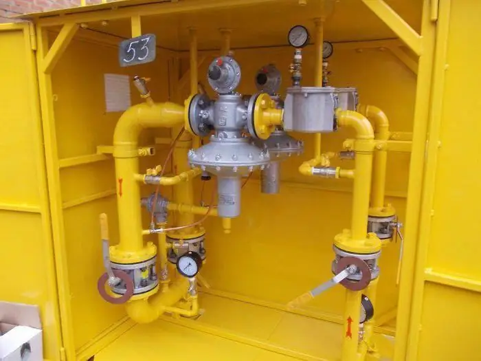
Classification
Fracs are subdivided depending on the method of equipment placement into the following types:
- Cabinet gas distribution points. In this case, the equipment is placed in cabinets made of fireproof materials.
- Gas control units. The equipment is mounted on a frame. It is placed in a room where the unit itself is used, or in a room that is connected to the units by an open opening.
- Gas distribution points block. In this case, the equipment is located in a container-type building (one or more).
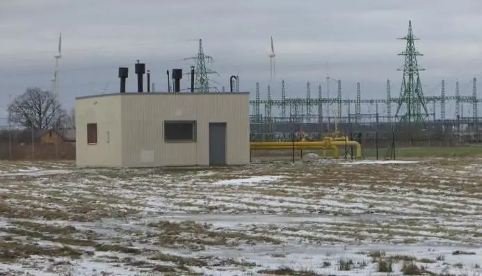
- Stationary gas distribution points. The equipment is placed in specially designed premises, structures or in open areas.
The fundamental difference between hydraulic fracturing of the latter type is that they do notare typical factory-ready products.
Requirements for production facilities
Gas distribution points with pressure up to 0.6 MPa at municipal and industrial enterprises, in boiler houses, standing separately, are located in buildings near the gas pipeline inlet, in rooms where gas-using equipment is located. GRU is forbidden to be installed under flights of stairs.
Establishment of gas distribution points in basements, semi-basements of structures, in annexes to buildings of hospitals, schools, children's institutions, administrative and residential buildings is not allowed.
Separately located hydraulic fracturing should have one floor and a combined roof. The roof must be easily dropped (the weight of 1 m of overlap is no more than 120 kg).
It is not allowed to install ventilation and smoke ducts in the separating ceilings and walls of structures to which the gas distribution point is attached. All rooms should be provided with artificial and natural lighting, a permanent ventilation system (natural) with three air exchanges.
Electric lighting and electrical equipment are made of explosion-proof materials. Inputs of power supply networks must be cable.
A telephone set can be placed in the regulatory hall. However, it must be protected from explosions.
Heating
When installing a local system, the heating installation is placed in an isolated room with a separate exit. It must be separated fromother premises of the gas distribution point with blank walls made of fire-resistant and gas-tight materials. The temperature of the coolant should be no more than 130, and the heating equipment - 95 degrees.
Protection against lightning should be provided for hydraulic fracturing. The floors are made of anti-spark materials.
Additional requirements
On the facade of the building in a conspicuous place put a warning sign "Flammable". Letters must be at least 300mm high.
Doors from the gas distribution point open outwards. The canvas is sheathed with galvanized steel (0.8 mm thick).
Equipment
It is placed taking into account the purpose of the hydraulic fracturing. The gas distribution point equipment includes:
- Pressure regulator that automatically reduces pressure and maintains it at a given level.
- Shut-off safety valve. With a decrease / increase in pressure, it automatically shuts off the gas supply.
- Reset safety device. It provides for the discharge of excess gas into the atmosphere, necessary to maintain the pressure level. The device is connected to the outlet gas pipeline or behind the flow meter (meter).
- Filter to eliminate mechanical impurities.
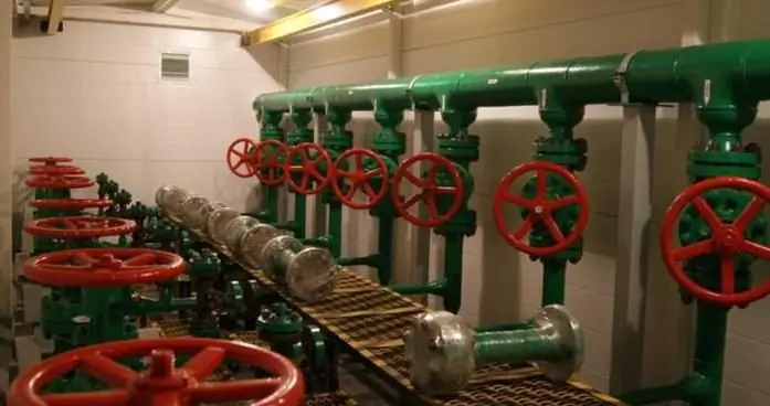
In front of the shut-off valve, a bypass (bypass gas pipeline) is installed with 2 shut-off devices located in series. Gas is supplied through the bypass during the inspection and repair of equipment on the linereduction. For points with a pressure of more than 0.6 MPa and a high (more than 5 thousand m / h) capacity, an additional control line is installed instead of a bypass gas pipeline.
Checking indicators
Using special measuring instruments, determine:
- Gas pressure before and after the regulator. For this, self-recording and indicating pressure gauges are used.
- Pressure drops across the gas filter. These indicators are checked by technical pressure gauges or differential pressure gauges.
- Gas temperature. To determine it, self-recording and indicating thermometers are used.
Purge and discharge pipelines
They are used to vent gas to the atmosphere and purge equipment. Purge lines installed at:
- Inlet gas pipeline behind the first connecting device.
- Bypass between locking mechanisms.
- Area with equipment shut down for repair and inspection.
Pipelines lead outside to places where safe gas dispersion is ensured (at least 1 m above the eaves of the structure).
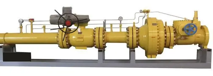
Locking devices should provide the ability to turn off the gas distribution point, measuring instruments and equipment without stopping the gas supply.
Regulators
Hydraulic fracturing can be one- or two-stage. In the first, the inlet pressure is regulated to the outlet by one, and in the second, respectively, by two regulators installed in series. Performancedevices should be approximately the same.
Single-stage models are used, as a rule, when the difference between the inlet and outlet pressures is within 0.6 MPa.
Impulse tapping areas for regulators and safety shut-off valves are defined in the equipment data sheet, but they are subject to change.
Commissioning of gas distribution points
It is carried out according to a written order recorded in a shift journal. Before starting, it is necessary to familiarize yourself with the content of the work that has been carried out since the shutdown, as well as the reasons for the termination of the hydraulic fracturing.
The launch is carried out in 2 stages:
- Inspection of equipment, instruments, fittings.
- Immediate launch.

Inspection
During it it is necessary to state:
- He althiness of control and measuring devices.
- Stability of pressure indicators (are within the limits of the norm). It is determined by opening the valve of the measuring device, showing the value of the inlet pressure.
- Completeness of the valve at the inlet. It should be closed.
- Serviceability and completeness of the filter.
- Safety shut-off valve included. The hammer and levers must be disengaged, the valve on the line to it must be closed.
- Faulty pressure regulator. The pilot propeller must be turned out, the valve on the line to it must be in the closed position.
Also on inspectionyou need to make sure that:
- At the input section of the production line, the valve is assembled and closed.
- The safety relief valve is in good condition, assembled, and the valve to it is in the open position.
- Both valves on the bypass are assembled, closed, the valve between them on the purge line is open.
Start fracturing
Sequentially opening:
- Purge valve.
- Cock on pressure gauge.
- Valves at the gas outlet from the point.
- Cock on the impulse line to the pressure regulating device.
Next Specialist:
- Engage safety shut-off valve levers.
- Slowly opens the valve at the inlet. Gas pressure must be at zero.
- Closes the bleed valve after the inlet valve.
- Slowly turns out the pilot screw of the regulating device, brings the pressure to working.
- Checks the stability of the regulator, opens the valve on the impulse line to the slam-shut valve and engages the hammer and rocker.
- Slowly closes the purge valve.
- Opens valves to working devices, checks for malfunctions, leaks.
The journal records the work done.
Recommended:
Arc steel furnace: device, operating principle, power, control system
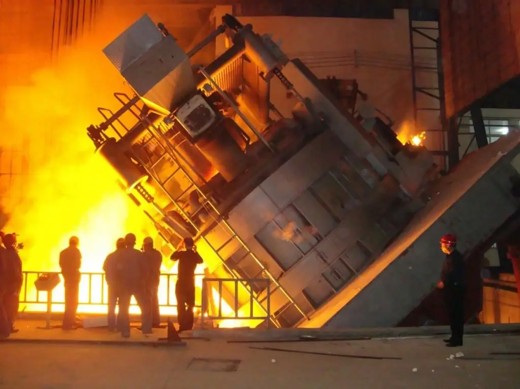
Arc steel-smelting furnaces (EAFs) differ from induction furnaces in that the loaded material is directly subjected to electrical bending, and the current at the terminals passes through the charged material
Diamond boring machine: types, device, operating principle and operating conditions
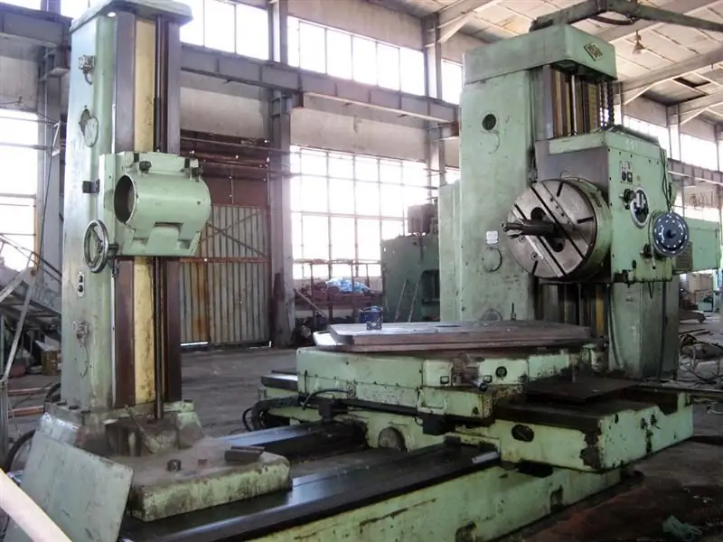
The combination of a complex cutting direction configuration and solid-state working equipment allows diamond boring equipment to perform extremely delicate and critical metalworking operations. Such units are trusted with the operations of creating shaped surfaces, hole correction, dressing of ends, etc. At the same time, the diamond boring machine is universal in terms of application possibilities in various fields. It is used not only in specialized industries, but also in private workshops
Duration of the operating cycle. What is an operating cycle?

The company will not have problems with a lack of current assets if the management begins to strictly control the proportions between equity and debt capital, through which operations are financed
Electricity distribution: substations, necessary equipment, distribution conditions, application, accounting and control rules
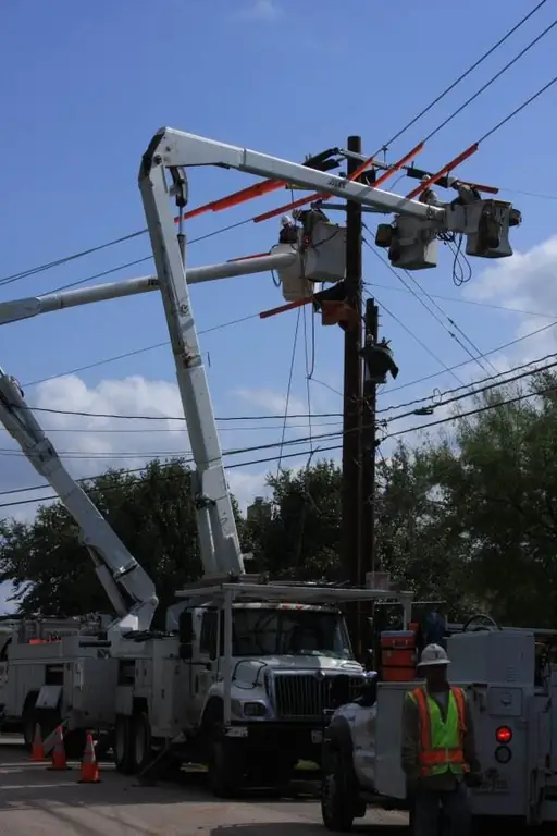
Everyone knows that electrical energy is supplied to the place of its consumption from a direct source. However, such sources can be located at a great distance from the consumer. Because of this, the distribution of electricity and its delivery is a rather complicated process
Laying a gas pipeline: methods, equipment, requirements. Gas pipeline security zone
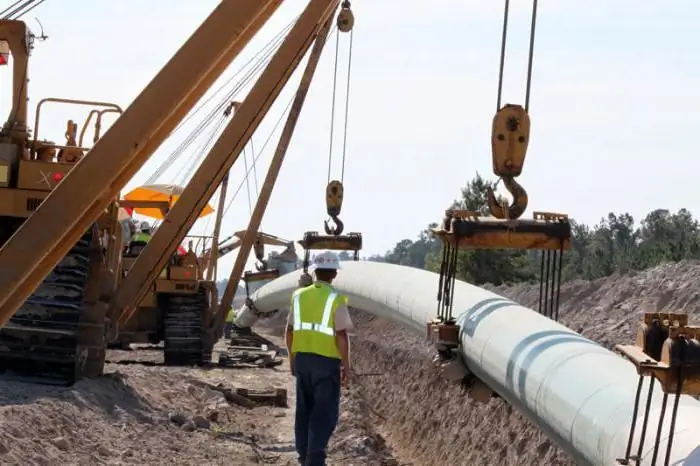
Laying of the gas pipeline can be done by underground and ground methods. When choosing equipment for such systems, safety standards should be followed. Actually, the laying of highways is carried out with strict observance of all the required technologies

