2026 Author: Howard Calhoun | calhoun@techconfronts.com. Last modified: 2025-01-24 13:10:43
Hydraulic mechanisms have been used by mankind since ancient times in solving various economic and engineering problems. The use of the energy of fluid flows and pressure is relevant today. The standard device of the hydraulic motor is calculated for the translation of the converted energy into a force acting on the working link. The very scheme of organization of this process and the technical and structural nuances of the execution of the unit have many differences from the usual electric motors, which is reflected in both the pros and cons of hydraulic systems.
Mechanism device
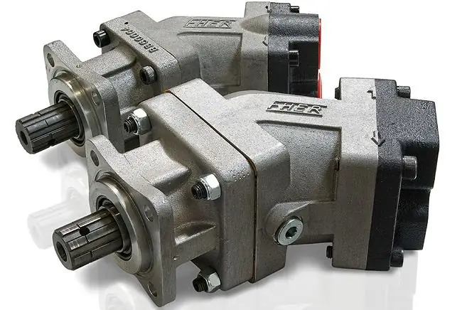
The design of the hydraulic motor is based on the housing, functional units and channels for moving fluid flows. The housing is usually mounted on support legs or fixed through locking devices with swivel capabilities. The main working element is the cylinder block, wherea group of pistons is placed, making reciprocating movements. To ensure the stability of this unit, the hydraulic motor device is provided with a system of constant pressure to the distribution disk. This function is performed by a spring with effective pressure from the working medium. The working shaft connecting the hydraulic motor with the output control is implemented as a splined or keyed assembly. Anti-cavitation and safety valves can be connected to the shaft as accessories. A separate channel with a valve provides liquid drainage, and in closed systems special circuits are provided for flushing and exchanging working media.
The principle of the hydraulic motor
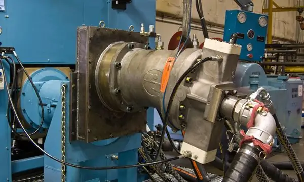
The main task of the unit is to ensure the process of converting the energy of the circulating fluid into mechanical energy, which, in turn, is transmitted through the shaft to the executive bodies. At the first stage of operation of the hydraulic motor, fluid enters the groove of the distribution system, from where it passes into the chambers of the cylinder block. As the chambers fill, the pressure on the pistons increases, resulting in the formation of torque. Depending on the specific device of the hydraulic motor, the principle of operation of the system at the stage of converting the pressure force into mechanical energy may be different. For example, the torque in axial mechanisms is generated due to the action of spherical heads and hydrostatic bearings on the thrust bearings, through which the operation of the cylinder block begins. At the final stage endsa cycle of injection and displacement of the liquid medium from the cylindrical group, after which the pistons begin to reverse action.
Connecting piping to hydraulic motor
At a minimum, the principle device of the mechanism should provide for the possibility of connecting to the supply and drain lines. Differences in how this infrastructure is implemented largely depend on valve adjustment techniques. For example, the device of the hydraulic motor of the EO-3324 excavator provides for the possibility of dividing flows with a shunt valve. To control the valve spools, a servo-driven control system with a pneumatic accumulator power supply is used.
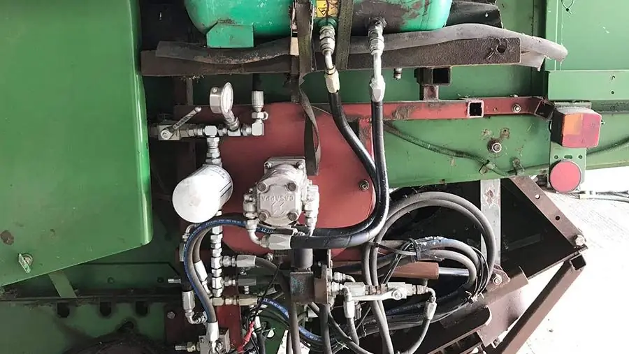
In conventional circuits, a drain hydraulic line is used, the pressure in which is regulated through an overflow valve. A distribution (also called a cleaning and flushing) spool with an overflow valve is used in hydraulic drives with closed flows for the exchange of working fluids within the circuit. A special heat exchanger and a cooling tank can be used as an addition to regulate the temperature regime of the liquid medium during the operation of the hydraulic motor. The device of the mechanism with natural regulation focuses on the constant injection of fluid at low pressure. The difference in pressure in the working lines of the hydraulic distribution system causes the control spool to move to a position where the low pressure circuit communicates with the hydraulic tank through the overflow valve.
Gear hydraulic motors
Suchmotors have much in common with gear pump units, but with a difference in the form of fluid removal from the bearing area. When the working medium enters the hydraulic motor, interaction with the gear begins, which creates a torque. The simple design and low cost of technical implementation made such a hydraulic motor device popular, although low performance (efficiency of the order of 0.9) does not allow it to be used in critical power supply tasks. This mechanism is often used in attachment control circuits, in machine tool drive systems and in providing the function of auxiliary bodies of various machines, where the rated speed of the working rotation is within 10,000 rpm.
Gerotor hydraulic motors
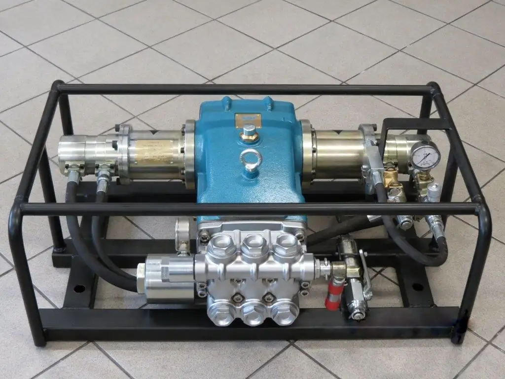
A modified version of gear mechanisms, the difference of which lies in the possibility of obtaining high torque with small dimensions of the structure. The liquid medium is serviced through a special distributor, as a result of which the toothed rotor is set in motion. The latter works on a roller run-in and begins to make a planetary movement, which determines the specifics of the gerotor hydraulic motor, the device, the principle of operation and the purpose of this unit. Its scope is determined by the high energy consumption under operating conditions at a pressure of about 250 bar. This is the optimal configuration for low-speed loaded machines, which also impose requirements on power engineering in terms of compactness and design optimization inoverall.
Axial piston motors
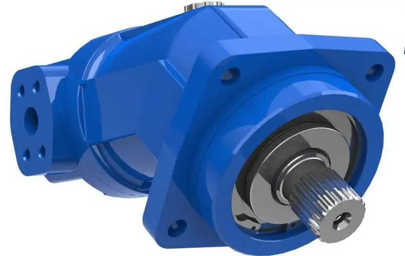
One of the variants of the rotary piston hydraulic machine, which most often provides for the axial placement of the cylinders. Depending on the configuration, they can be located around, parallel or with a slight slope with respect to the axis of rotation of the piston group block. The device of the axial-piston hydraulic motor assumes the possibility of a reverse stroke, therefore, in layouts with serviced units, it is necessary to connect a separate drain line. As for the target equipment operating such engines, it includes hydraulic machine drives, hydraulic presses, mobile working units and various equipment operating with a torque of up to 6000 Nm at a high pressure of 400-450 bar. The volume of the served environment in such systems can be both constant and adjustable.
Radial piston motors
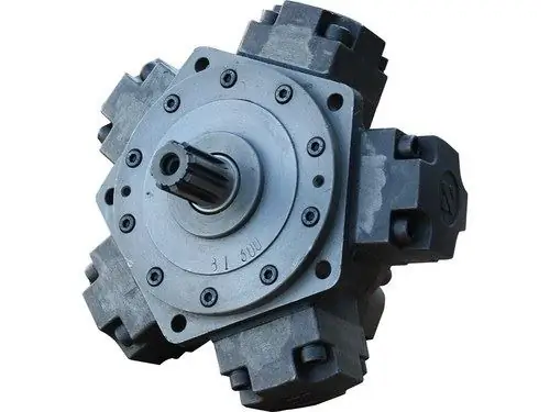
Most flexible and balanced hydraulic motor design in terms of high torque control. Radial piston mechanisms are available with single and multiple action. The former are used in screw lines for the movement of liquids and loose suspensions, as well as in rotary units of production conveyors. The radial piston device and the principle of operation of a single-acting hydraulic motor can be reflected in the following functional cycle: under high pressure, the working chambers begin to act on the drive fist, thus starting the rotation of the shaft,transmitting effort to the executive link. An obligatory structural element is the distributor for draining and supplying liquid, coupled with the working chambers. Multiple action systems are just distinguished by a more complex and developed mechanics of the interaction of chambers with a shaft and channels for distributing liquid. In this case, there is a clear divided coordination within the function of the distribution system for individual cylinder blocks. Individual regulation on the circuits can be expressed both in the simplest commands to turn on / off valves, and in a point change in the parameters of pressure and volume of the pumped medium.
Linear hydraulic motor
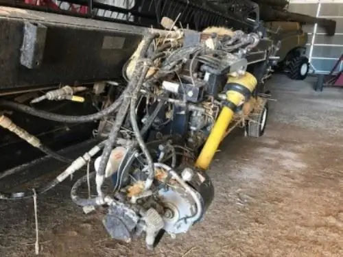
A variant of a positive displacement hydraulic motor that generates only incoming movements. Such mechanisms are often used in mobile self-propelled machinery - for example, in a combine harvester, a hydraulic motor supports the function of the executive units due to the energy of an internal combustion engine. From the main output shaft of the power plant, energy is directed to the shaft of the hydraulic unit, which, in turn, provides mechanical energy to the organs for harvesting grain. In particular, the linear hydraulic motor is capable of developing pulling and pushing forces over a wide range of pressures and working areas.
Conclusion
Hydraulic power machines have many positive operating points, which manifest themselves in different ways depending on the specific design of the unit. So ifthe gerotor device of the hydraulic motor is simple and does not require serious maintenance costs, then the axial and radial designs in new versions are more designed to achieve high torques and maintain appropriate power indicators, but are more expensive to maintain. For a number of universal indicators, there are general advantages of hydraulic machines over battery, electric and diesel devices, but they also have weaknesses, which are expressed in relatively low efficiency and dependence on indirect factors of the work process. This concerns the sensitivity of hydraulics to temperature changes, the viscosity of the working medium, pollution, etc.
Recommended:
Hydraulic system: calculation, scheme, device. Types of hydraulic systems. Repair. Hydraulic and pneumatic systems
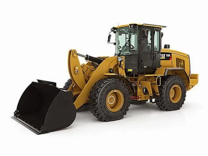
The hydraulic system is a special device that works on the principle of a liquid lever. Such units are used in the braking systems of cars, in loading and unloading, agricultural machinery and even in the aircraft industry
Classification of engines. Types of engines, their purpose, device and principle of operation
Nowadays, most vehicles are powered by an engine. The classification of this device is huge and includes a large number of different types of engines
Driver controller: purpose, device and principle of operation
The use of a variety of vehicles today is very active. They all have in common that they need to be managed. The driver's controller is also designed for control. With it, you can remotely control the traction motor in braking or traction mode
Hydraulic press: description, device, principle of operation, characteristics
Processing various materials under strong physical pressure allows you to perform stamping, cutting, straightening and other operations. Similar works are organized in construction, in production, in the transport sector and car services. Technical conditions for them are most often created by means of a hydraulic press, which is controlled directly by the operator without power auxiliary units
Reservoir breathing valve: purpose, device, principle of operation, verification
Oil refineries and technological complexes using oil and gas products contain a system of pipelines for servicing fuel materials in their working infrastructure. Maintaining sufficient performance in the circulation circuits of the same oil requires the use of special plumbing fittings. Its key element is the reservoir breather valve, through which the pressure is regulated

