2026 Author: Howard Calhoun | [email protected]. Last modified: 2025-01-24 13:10:39
Protection devices are devices that are designed to protect electrical circuits, electrical equipment, machines and other units from any threats that interfere with the normal operation of these devices, as well as to protect them from overloads. It is important to note here that they must be installed correctly, and the operation must be carried out exactly in accordance with the instructions, otherwise the protection devices themselves can cause equipment failure, explosion, fire and other things.
Basic fixture requirements
In order for the device to operate successfully, it must meet the following requirements:
- Protection devices must not, under any circumstances, be allowed to exceed the temperature allowed for them under normal load of the electrical network or electrical equipment.
- The device should not disconnect the equipment from power during short-term overloads, which often include inrush current, self-starting current, etc.
When choosing fuse links, you must be based on the rated current in the section of the circuit that will protect this device. This rule for choosing protection devices is relevant in any case when choosing any device for protection. It is also important to understand that with prolonged overheating, the protective qualities are significantly reduced. This negatively affects the devices, since at the moment of critical load they may, for example, simply not turn off, which will lead to an accident.
Protection devices must necessarily turn off the network when prolonged overloads occur within this circuit. In this case, the inverse dependence on the current in terms of the exposure time must be observed.
In any case, the protection device must disconnect the circuit at the end when a short circuit (short circuit) occurs. If a short circuit occurs in a single-phase circuit, then the shutdown must occur in a network with a solidly grounded neutral. If a short circuit occurs in a two-phase circuit, then in a network with isolated neutral.
Electric circuit protection devices have a breaking capacity I pr. The value of this parameter must correspond to the short-circuit current that may occur at the beginning of the protected section. If this value is lower than the maximum possible short circuit current, then the process of disconnecting a section of the circuit may not occur at all or may occur, but with a delay. Because of this, not only the devices connected to this network can be damaged, but also the electrical circuit protection device itself. For this reason, the breaking factor must begreater than or equal to the maximum short circuit current.

Fusible Type Fuses
Today, there are several devices for protecting electrical networks, which are the most common. One of these devices is a fuse. The purpose of this type of protection device is that it protects the network from current-type overloads and short circuits.
Today, there are disposable devices, as well as with interchangeable inserts. Such devices can be used both in industrial needs and in everyday life. To do this, there are devices that are used in lines up to 1 kV.
Besides them, there are high-voltage devices used in substations, the voltage of which is more than 1000 V. An example of such a device can be a fuse on auxiliary transformers of substations with 6/0, 4 kV.
Since the purpose of these protection devices is to protect against short circuits and current overloads, they have been widely used. In addition, they are very simple and easy to use, their replacement is also quick and easy, and they are very reliable in themselves. All this has led to the fact that such fuses are used very often.
To consider the technical characteristics, you can take the device PR-2. Depending on the rated current, this device is available with six types of cartridges, which differ in their diameter. In the cartridge of each of them, an insert can be installed with the expectation of a different rated current. Tofor example, a 15 A cartridge can be equipped with an insert for both 6 A and 10 A.
In addition to this characteristic, there is also the concept of lower and upper test current. As for the lower value of the test current, this is the maximum value of the current, during the flow of which in the circuit for 1 hour the circuit section will not be disconnected. As for the upper value, this is the minimum current coefficient that, when flowing for 1 hour in the circuit, will melt the insert in the protection and control apparatus.

Circuit breakers
Circuit breakers play the same role as fuses, but their design is more complex. However, this is offset by the fact that switches are much more convenient to use than fuses. For example, if a short circuit appears in the network due to aging of the insulation, then the switch is able to disconnect the damaged section of the electrical circuit from power. At the same time, the control and protection apparatus itself is quite easily restored, after operation it does not require replacement with a new one, and after repair work it is able to reliably protect the section of the circuit under its control again. It is very convenient to use this kind of switches if it is necessary to carry out any routine repairs.
As for the production of these devices, the main indicator is the rated current for which the device is designed. In this regard, there is a huge choice, which allows you to choose the most suitable for each chain.device. If we talk about the operating voltage, then they, like fuses, are divided into two types: with voltage up to 1 kV and high-voltage with an operating voltage above 1 kV. It is important to add here that high-voltage protection devices for electrical equipment and electrical circuits are produced in vacuum, with an inert gas or oil-filled. This design allows at a higher level to disengage the circuit when such a need arises. Another significant difference between circuit breakers and fuses is that they are made for operation not only in single-phase, but also in three-phase circuits.
For example, in the event of a short circuit to the ground of one of the conductors of an electric motor, the circuit breaker will turn off all three phases, and not one damaged one. This is a significant and key difference, because if only one phase is turned off, the motor will continue to operate on two phases. This mode of operation is an emergency and greatly reduces the life of the device, and may even lead to an emergency failure of the equipment. In addition, automatic type circuit breakers are manufactured to work with both AC and DC voltage.

Thermal and current relay
Today, there are many different types of relays among electrical network protection devices.
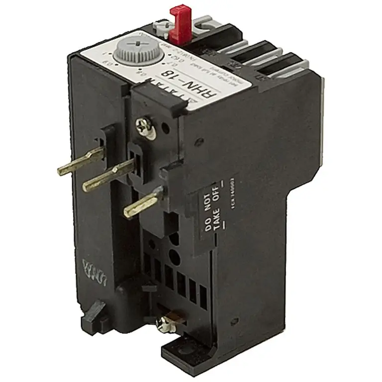
The thermal relay is one of the most common devices that can protect electric motors, heaters, any power devices fromproblem such as overload current. The principle of operation of this device is very simple, and it is based on the fact that electric current is able to heat the conductor through which it flows. The main working part of any thermal relay is a bimetallic plate. When heated to a certain temperature, this plate bends, which breaks the electrical contact in the circuit. Naturally, the heating of the plate will continue until it reaches the critical point.
In addition to thermal, there are other types of protection devices, for example, a current relay that controls the amount of current in the network. There is also a voltage relay that will respond to a change in voltage in the network and a differential current relay. The last device is a leakage current protection device. It is important to note here that circuit breakers, like fuses, cannot react to the occurrence of current leakage, since this value is quite small. But at the same time, this value is quite enough to kill a person in contact with the case of a device subject to such a malfunction.
If there are a large number of electrical appliances that need to connect a differential current relay, then combined machines are often used to reduce the size of the power shield. Devices that combine a circuit breaker and a differential current relay - differential protection circuit breakers, or difautomats, have become such devices. When using such devices, not only the size of the power shield is reduced, but the installation process is greatly facilitated.protection apparatus, which in turn makes them more economical.

Thermal Relay Specifications
The main characteristic for thermal relays is the response time, which depends on the load current. In other words, this characteristic is called time-current. If we consider the general case, then before the load is applied, the current I0 will flow through the relay. In this case, the heating of the bimetallic plate will be q0. When checking this characteristic, it is very important to consider from which state (overheated or cold) the device is triggered. In addition, when checking these devices, it is very important to remember that the plate is not thermally stable when a short circuit current occurs.
The choice of thermal relays is as follows. The rated current of such a protective device is selected based on the rated load of the electric motor. The selected relay current should be 1, 2-1, 3 of the motor rated current (load current). In other words, such a device will work if within 20 minutes the load is from 20 to 30%.
It is very important to understand that the operation of the thermal relay is significantly affected by the ambient air temperature. Due to the increase in ambient temperature, the operating current of this device will decrease. If this indicator differs too much from the nominal, then it will be necessary either to carry out additional smooth adjustment of the relay,or buy a new device, but taking into account the actual ambient temperature in the working area of \u200b\u200bthis unit.
To reduce the effect of ambient temperature on the pickup current value, it is necessary to purchase a relay with a higher load rating. In order to achieve the correct functioning of a warm device, it should be installed in the same room as the controlled object. However, it must be remembered that the relay responds to temperature, and therefore it is prohibited to place it near concentrated heat sources. Boilers, heating sources and other similar systems and devices are considered to be such sources.

Select devices
When choosing equipment for protecting electrical receivers and electrical networks, it is necessary to be based on the rated currents for which these devices are designed, as well as on the current supplying the network where such units will be installed.
When choosing a protection device, it is very important to keep in mind the occurrence of such abnormal operating modes as:
- phase-to-phase short circuits;
- phase short to case;
- a strong increase in current, which can be caused by an incomplete short circuit or an overload of process equipment;
- complete disappearance or too much reduction in voltage.
As for short circuit protection, it must be carried out for all electrical receivers. The main requirement is that disconnecting the device from the network whenthe occurrence of a short circuit should be the minimum possible. When choosing protective devices, it is also important to know that full overcurrent protection must be provided, with the exception of a few of the following cases:
- when overloading electrical receivers for technological reasons is simply impossible or unlikely;
- if the power of the electric motor is less than 1 kW.
In addition, an electrical protection device may not have an overload protection function if it is installed to monitor an electric motor that is operated in intermittent or intermittent operation. An exception is the installation of any electrical appliances in rooms with a high fire hazard. In such rooms, overload protection must be installed on all devices without exception.

Undervoltage protection must be set in some of the following cases:
- for electric motors that cannot be switched on at full voltage;
- for electric motors where self-starting is not allowed for a number of technological reasons, or it is dangerous for employees;
- for any other electric motors that need to be turned off to reduce the total power of all connected electrical receivers on this network to an acceptable value.
Varieties of currents and selection of protective device
The most dangerous is the short circuit current. The main danger is that it is much larger than the normal starting current, and also its value can vary greatly depending on the section of the circuit where it occurs. Thus, when testing a protection device that protects a circuit from a short circuit, it must, as quickly as possible, disconnect the circuit when such a problem occurs. At the same time, in no case should it work when a normal value of the starting current of any electrical device occurs in the circuit.
As for the overload current, everything is pretty clear here. Such a current is any value of the characteristic that exceeds the rated current of the electric motor. But here it is very important to understand that not every time an overload current occurs, the protective device must disconnect the contacts of the circuit. This is also important because a short-term overload of both the electric motor and the electrical network is permissible in some cases. It is worth adding here that the shorter the load, the greater the values it can reach. Based on this, it becomes clear what is the main advantage of some devices. The degree of protection of devices with a "dependent characteristic" in this case is the maximum, since their response time will decrease with an increase in the load factor at this moment. Therefore, such devices are ideal for overcurrent protection.

To summarize, we can say the following. For protection againstshort circuit, an inertia-free device must be selected, which will be configured to operate a current that is significantly higher than the starting value. For overload protection, on the contrary, the protection switching device must have inertia, as well as a dependent characteristic. It must be selected in such a way that it does not operate during the normal start-up of the electrical device.
Disadvantages of different types of protective devices
Fuses, which were previously widely used as switchgear protection devices, have the following disadvantages:
- rather limited possibility for use as overcurrent protection as inrush current detuning is quite difficult;
- motor will continue to run on two phases even if the third is cut off by a fuse, causing the motor to fail frequently;
- in certain cases, the cut-off power limit is insufficient;
- no ability to quickly restore power after a power outage.
As for the air types of machines, they are more perfect than fuses, but they are not without drawbacks. The main problem with the use of electrical protection devices is that they are not selective in terms of action. This is especially noticeable if an unregulated cutoff current occurs at the setting machine.
There are installation machines in which overload protection is carried out using thermal releases. Sensitivity andtheir delay is worse than that of thermal relays, but at the same time they act on all three phases at once. As for universal automatic machines for protection, here it is even worse. This is justified by the fact that only electromagnetic releases are available.
Magnetic starters are often used, in which thermal type relays are built. Such protective equipment is able to protect the electrical circuit from overload current in two phases. But since thermal relays have a large inertia, they are not able to provide protection against short circuits. Installing a holding coil in the starter can provide undervoltage protection.
High-quality protection against both overload current and short circuit can only be provided by induction relays or electromagnetic relays. However, they can only work through a disconnecting device, which makes the circuit with their connection more complicated.
Summarizing the above, we can draw the following two conclusions:
- To protect electric motors, whose power does not exceed 55 kW, from overload current, magnetic starters with fuses or with air devices are most often used.
- If the power of the electric motor is more than 55 kW, then electromagnetic contactors with air vehicles or protective relays are used to protect them. It is very important to remember here that the contactor will not allow the circuit to be broken if a short circuit occurs.
When choosing the right device, it is very important to calculate the protection devices. The most important formula is the calculation of the rated current of the motor, which will allow you to choose a protection device with suitable indicators. The formula looks like this:
In=Rdv ÷(√3Uncos c n), where:
In is the rated current of the motor, which will be in A;
Rmotor is the power of the engine, which is represented in kW;
Un is the rated voltage in V;
cos q is the active power factor;
n is the efficiency factor.
Knowing these data, you can easily calculate the rated current of the motor, and then easily select the appropriate protection device.
Varieties of damage to protective equipment
The main difference between electrical circuit protection devices and other devices is that they not only fix the defect, but also disconnect the circuit if the characteristic values go beyond certain limits. The most dangerous problem, which often disables protective equipment, has become a dull short circuit. During the occurrence of such a short circuit, the current indicators reach the highest values.
When an open circuit occurs when such a problem occurs, an electric arc often occurs, which in a short period of time is quite capable of destroying the insulation and melting the metal parts of the apparatus.
If too much overload current occurs, it may cause the conductive parts to overheat. In addition, there are mechanical forces thatsignificantly increase the wear of individual elements of the equipment, which can sometimes even lead to breakage of the device.
There are high-speed circuit breakers that are prone to such problems as rubbing the movable arm and the movable contact against the walls of the arc chute, as well as shorting the demagnetizing coil bar to the case. Quite often there is too much wear on the contact surfaces, pistons and drive cylinders.
Repair of high-speed machines
Repair of any type of high-speed protection device must be carried out in the same sequence. The high-speed switch, or BV, is blown with clean compressed air at a pressure of not more than 300 kPa (3kgf/cm2). After that, the device is wiped with napkins. Next, you need to remove items such as the arc chute, blocking device, pneumatic actuator, moving contact armature, inductive shunt, and others.
Direct repair of the device is carried out at a special repair stand. The arc chute is disassembled, its walls are cleaned in a special shot blasting machine, after which they are wiped and inspected. In the upper part of this chamber, chips can be allowed if their dimensions do not exceed 50x50 mm. The wall thickness at the points of rupture should be from 4 to 8 mm. It is necessary to measure the resistance between the horns of the arc chute. For some samples, the indicator must be at least 5 MΩ, and for some, at least 10 MΩ.
The damaged partition must be cut downits entire length. All similar places of fellings should be carefully cleaned. After that, the surfaces to be bonded are lubricated with an adhesive solution based on epoxy resin. If broken fan sheets were found, they are replaced. If there are bent ones, they must be leveled and returned to service. There is also an arc chute, which should be cleaned of deposits and melting, if any.
Recommended:
Classification of engines. Types of engines, their purpose, device and principle of operation
Nowadays, most vehicles are powered by an engine. The classification of this device is huge and includes a large number of different types of engines
Machines for furniture production: types, classification, manufacturer, characteristics, instructions for use, specification, installation and operation features
Modern equipment and machines for furniture manufacturing are software and hardware tools for processing blanks and fittings. With the help of such units, craftsmen perform cutting, edging and adding parts from MDF, chipboard, furniture board or plywood
Artificial structures: types, classification, construction, maintenance, operation and repair

The concept of "artificial structures" is used as a generic name for various objects that are erected at the intersection of roads with rivers, streams, other transport lines, melt and rainwater flows, deep gorges, urban areas, mountain ranges. What is all this for?
Electric locomotive 2ES6: history of creation, description with photo, main characteristics, principle of operation, features of operation and repair
Today, communication between different cities, passenger transportation, delivery of goods is carried out in a variety of ways. One of these ways was the railroad. Electric locomotive 2ES6 is one of the types of transport that is currently actively used
Steel support: types, types, characteristics, purpose, installation rules, operation features and applications
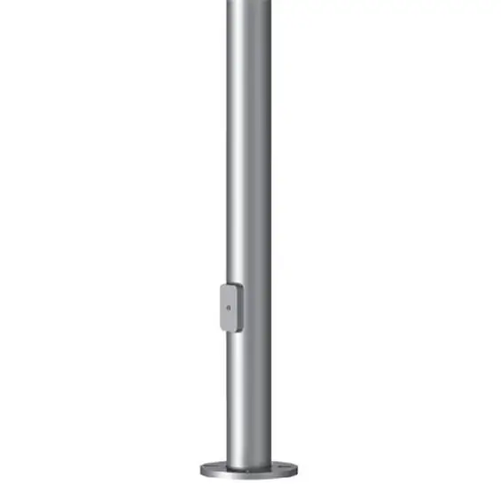
Steel poles today are most often used as lighting poles. With their help, they equip the lighting of roads, streets, courtyards of residential buildings, etc. In addition, such structures are often used as supports for power lines

